This is Part 6 in an on-going series of tutorials that will teach you how to build a Bussmann RTMR fuse/relay block for your vehicle. Previous articles discussed parts, tools, and assembly for the enclosure. If you’ve been following along, then you should have a completed Bussmann RTMR fuse/relay block that is ready for installation.
In this part, there will be a modest amount of fabrication, and I’ll talk about switches in more detail. This will include detailed instruction on how to connect your switches, power supply, and grounds. I’ll be using my 2015 Toyota Tacoma for an installation example, so some details will vary with your vehicle. However, I’m hoping that after reading this you’ll have a basic understanding of how to install the Bussmann RTMR that you can adapt to your needs.
This part will outline the following:
- Switch Panel Fabrication
- Switch wiring
- Wiring harness installation
- Electrical connections
- Final installation
And as a reminder, I take no responsibility for damage, accidents, or injuries resulting from the fabrication or installation of any electrical modifications to your vehicle. You do so at your own risk.
Switch Panel Fabrication
Let’s begin by building the switch panel. For this project, I chose to install the switch panel in the overhead console sun-glass compartment. My 2015 Toyota Tacoma has two sun-glass holders in the overhead console, and I chose to install the switch panel in the compartment closest to the rear of the vehicle. This is a tight fit and prohibits the use of switch backs. Additionally, I haven’t tested if this setup would work in the other compartment, but I’ve heard that it should.
Parts used in this section:
- Switch holder: Six Position V-Series Switch Holder
- Quantity: 1
- Switches: Carling Technologies, Contura V
- Quantity: 5
- Switch blank: V-Series Panel Plug
- Quantity: 1
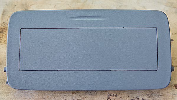
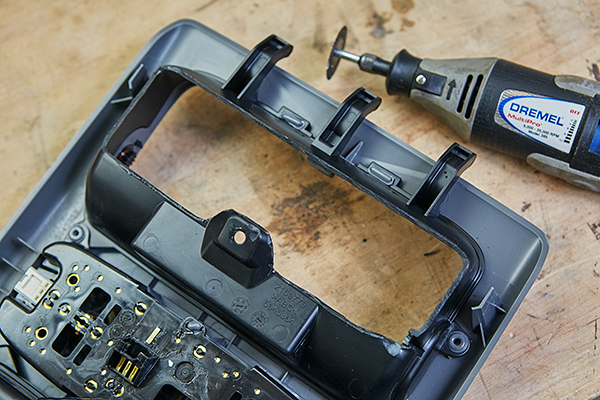
Remove the overhead console with the sun-glass compartments from your vehicle. At a workbench, detach the sun-glass holder which would be closest to the rear of the vehicle, and set the overhead console aside. Using the switch holder as a template, mark the outline of the switch housing with a Sharpie pen.
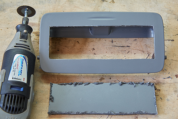
With a Dremel tool, cut the hole. I found it easy to cut in two passes. First, lightly score the line, and then cut all the way through on the second pass.
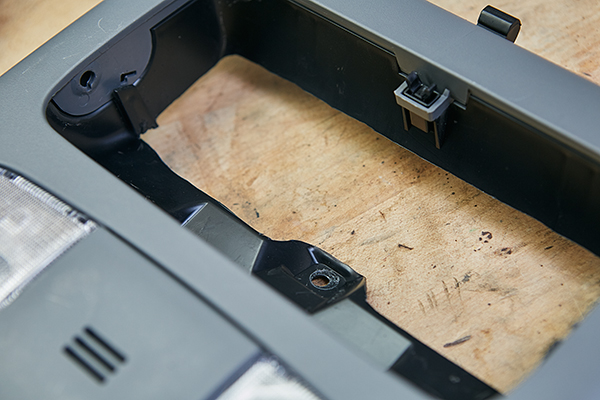
The switch housing is easily snapped into place.
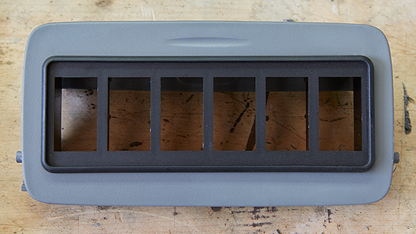
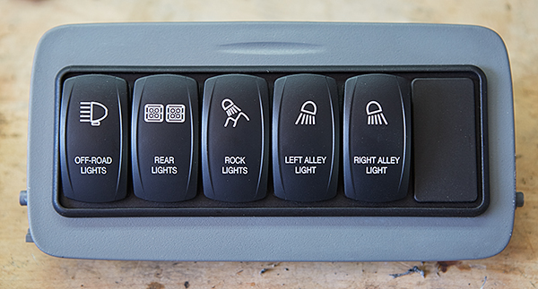
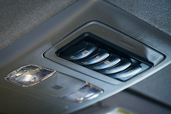
Finally, insert your switches in whatever position you desire along with the switch blank.
There is very limited space in the sun-glass holder compartment to accommodate the wiring. Therefore, we need to modify the backside of the overhead console to make more room. There’s really no accuracy here. Simply use your Dremel tool with a cut-off wheel and hack it. I removed as much as I could while retaining the mounting points.
From the inside, it should look similar to this.
Switch Wiring
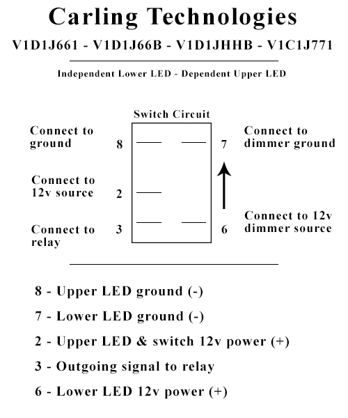
The switches I’m using for this tutorial are made by Carling Technologies and were purchased at OTRATTW. They are Contura V switches with an independent lower LED and a dependent upper LED. This means that the lower LED is not controlled by the switch itself. Instead, this installation will show you how to wire the lower LED so that it’s controlled along with the same circuit as your vehicles dash lighting. Therefore, it will be dimming. The upper LED is controlled by the switch and will illuminate when the switch is on.
If you choose to use a different switch that either eliminates the LEDs or reverses the positions, then I suggest you read through this section and adjust accordingly. The terminals should be the same but in different positions.
This section will show you how to make a wire harness that supplies power and ground to all your switches as well as the signal wire to your relays. Study the following diagram of the back of a Contura V switch and familiarize yourself with the terminals. This diagram indicates the necessary wire connections, which we will make shortly.
Now that you understand how to connect one switch, it’s easy to wire multiple switches in a panel. By making individual wire harnesses for power sources and ground, these can be installed to jumper the switches together. This allows us to have a single source or ground wire for all five switches instead of separate power and ground wires for each switch. Taking a look at the diagram again, you’ll notice that each switch requires two power sources and two grounds. Therefore, we need to make a total of four wire assemblies that provide power or ground and that jumper the switches to each other.
As a side note, if you’re installing the switch panel in a different location and plan on using switchbacks, then the wire connections will be identical. Instead of connecting to the back of the switches, they will connect to the rear of the switchbacks. My suggestion is that you read this section and adjust accordingly after you understand the process.
Parts used in this section:
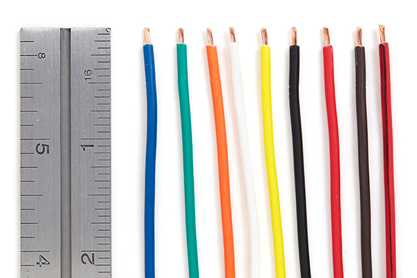
- Wire: 18 AWG GXL
- Colors: black, red, brown, red/black, blue, green, orange, white, yellow
- Quantity: 19″ each color
- Molex Mini-Fit Jr. connector: female, 10-position
- Quantity: 1
- Molex Mini-Fit Jr. terminals: female
- Quantity: 9
- Female Quick Disconnects: 20-18 AWG, 1/4″
- Quantity: 25
- Heat shrink: 1/2″ adhesive-lined
- Quantity: 5″
Begin by cutting four lengths of 18AWG wire, 2 1/4″ long, for each color: black, brown, red, and red/black.
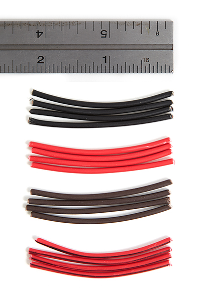
Strip each end of all wires 1/4″.
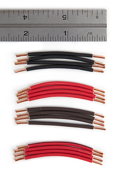
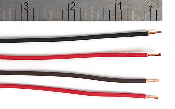
Then cut four wires 10″ long of the same color: black, brown, red, and red/black.
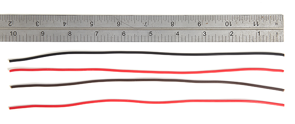
Strip one end of each wire 1/4″.
We will make all four wire assemblies before making any connections. So you can start with any color. Pick a color, and begin by twisting the 10″ long wire together with one of the 2 1/4″ long wires.
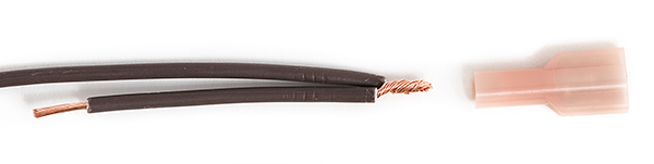
Crimp them together. I’m using 22-18AWG insulated female quick-disconnects. Technically, these are the incorrect size when twisting two 18AWG wires together. But they worked in my situation. If you find that they won’t accept the wire, step up a size to 16-14AWG connectors.
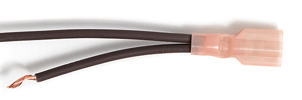
Next, using another 2 1/4″ length wire, twist the ends together as follows. Notice how I positioned the second wire. This is done so that when the assembly is connected to the switches, they install nice and flat without any twists.
Crimp on the second connector.
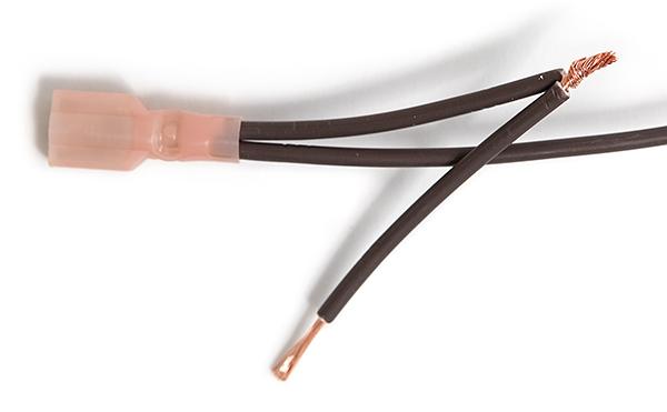
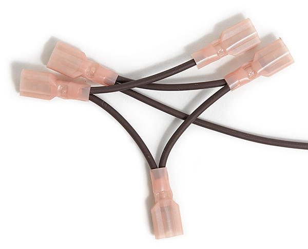
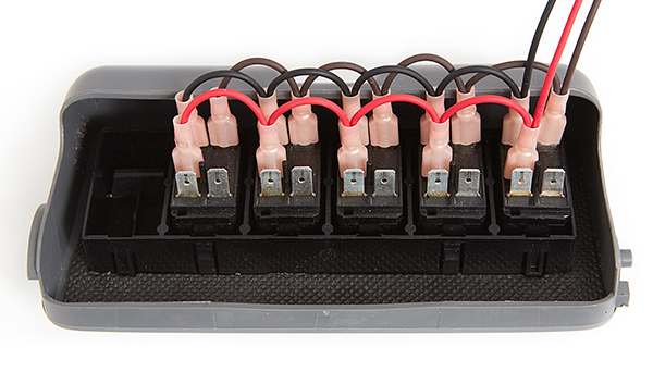
Continue in this fashion until you reach the last wire, where you simply crimp on the fifth and last connector. When complete, the assembly should look similar to the following.
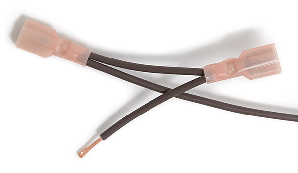
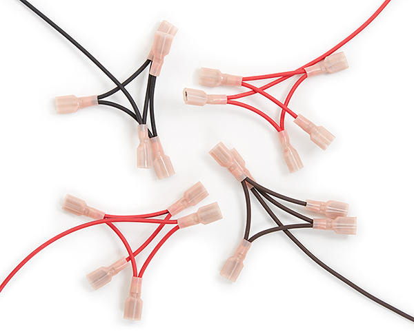
With the exact same process, make three additional wire assemblies with the other colors. You’ll end up with four completed wire assemblies as follows:
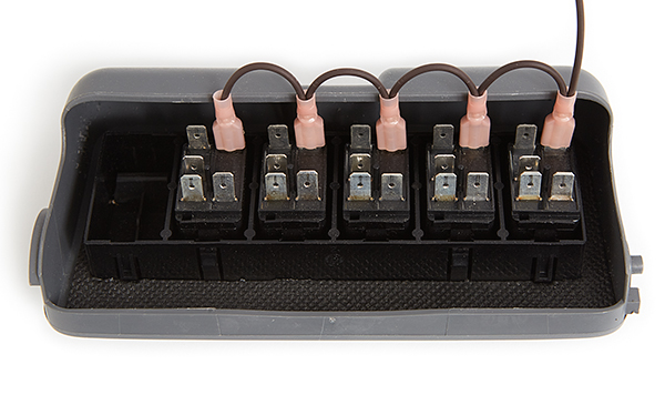
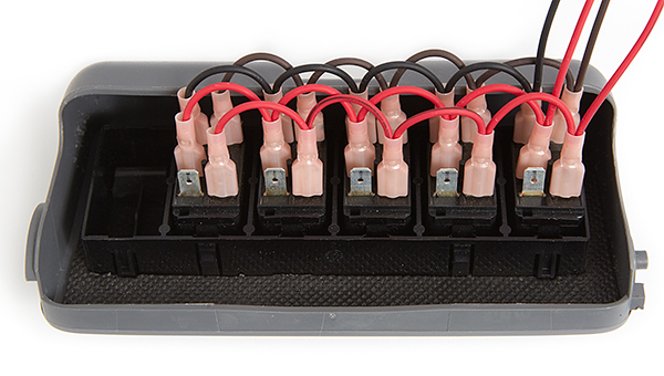
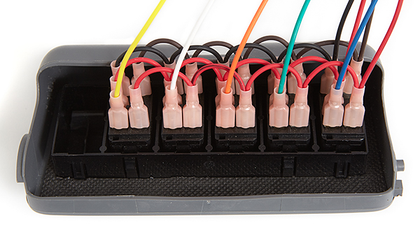
Now it’s time to make your connections. The first connection will be to the lower independent LED. This is the light that illuminates when your dash lights are on. Begin with the brown wire to terminal #7 on the switches. Insert the terminal with the 10″ wire to the first switch and continue across to the additional switches. It should look like the following when complete.
The ground for the upper dependent LED is through terminal #8. Use the black wire assembly for this and connect to terminal#8 in the same manner as the brown, with the long wire connected to the first switch.
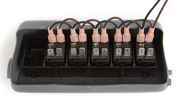
The power source to the switches, which illuminates the upper dependent LED and that sends power to the relays in your Bussmann RTMR, is connected to terminal #2. Use the red wire assembly and connect similarly as before.
Finally, connect the power source for the lower independent LED to terminal #6 using the red/black wire assembly.
The last terminal connection is for the signal wire that connects to the relays in your Bussmann RTMR. Cut five individually colored 18AWG wires 10″ long: blue, green, orange, white, and yellow.
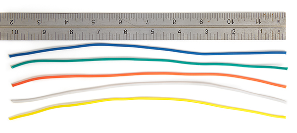
Strip one end of each wire 1/4″.
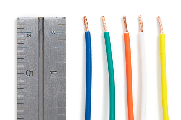
Crimp a 22-18AWG female connector to each wire.
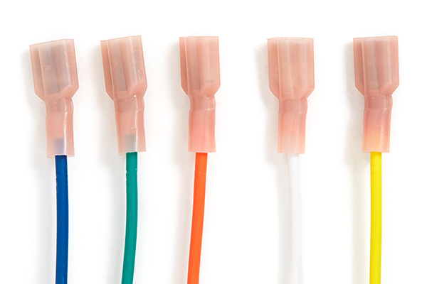
Connect the wires to terminal #3 of each switch in the same order as we did in the switch harness when building the RTMR: blue, green, orange, white, and yellow.
Now that the terminal connections are made, we’re at a point where a decision has to be made. If you recall from Part 5, we made a long wire harness that plugs into the Bussmann RTMR and will travel through the firewall to the switch panel. Your decision is in how to connect that harness to the switch panel that you just wired.
If you’re using switchbacks, then you very well could wire the long harness to the switchbacks directly with jumper wires joining them all together. Another simple option is to use butt splice connectors. A final option is to use a connector of some sort, which is my preference so that the installation maintains flexibility and allows the overhead console to be removed in the future for any reason. My choice in connectors is a Molex Mini-Fit Jr. 10-position connector, and as this tutorial continues, I will outline the use of Molex connectors and terminals.
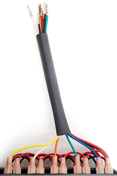
Begin by cutting a piece of 1/2″ heat shrink tubing about 5″ long.
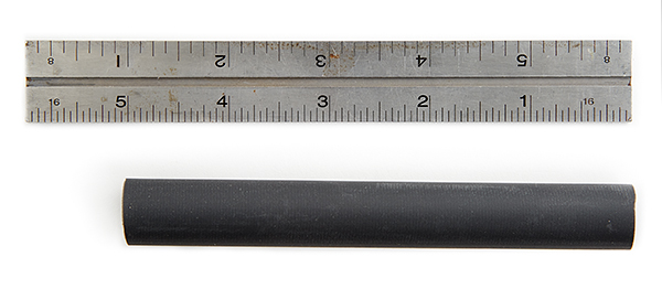
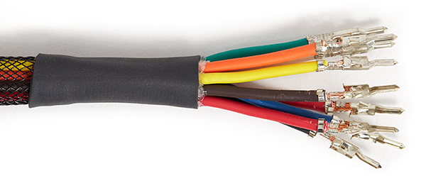
Grab all the loose wiring together and temporarily slip on the shrink tubing. Cut the wires evenly so that they hang over about an inch. Afterwards, remove the tubing and set aside for later.
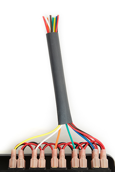
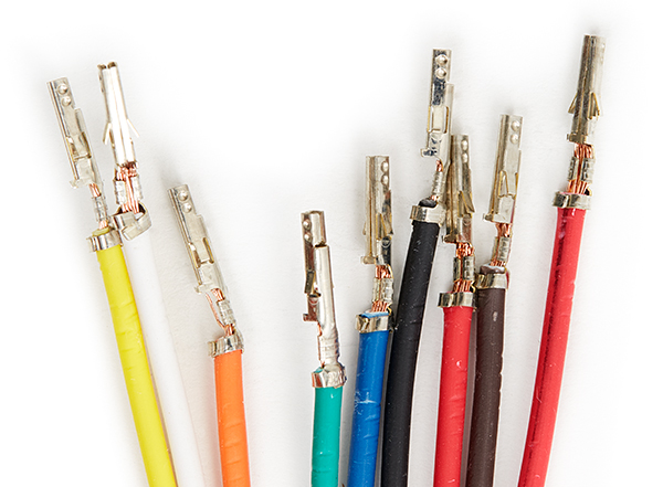
Begin by stripping each wire 3/16″ to accept the female Mini-Fit Jr. Molex terminals.
Crimp female terminals to each wire.
Using the heat shrink tubing that you set aside, slip over the wiring but don’t shrink in place yet. We want to insert the terminals into the plug first.
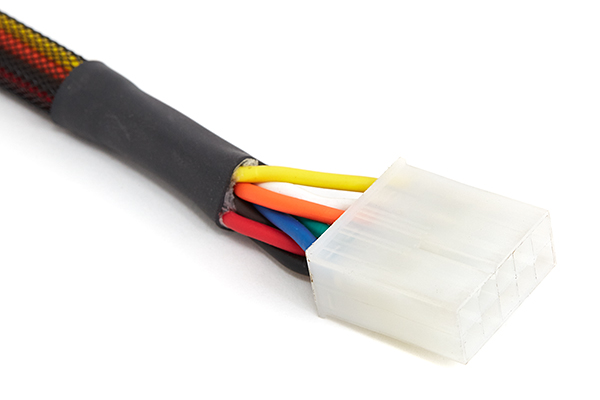
Insert the terminals into the Molex Mini-Fit Jr. female connector as follows, which has small numbers embossed on the connector for each wire opening. If you don’t have enough slack in the wires to insert the terminals, trim the tubing a bit and try again.
- blue
- green
- orange
- white
- yellow
- ——–
- black
- red
- brown
- red/black
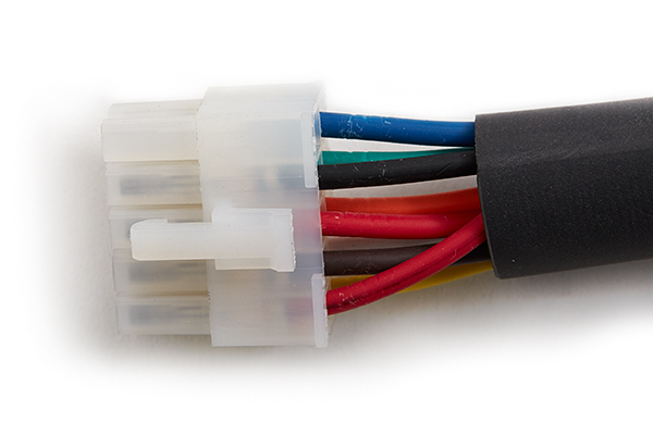
Finally, use a heat gun to shrink. When complete, it should look like this.
Wire Harness Installation
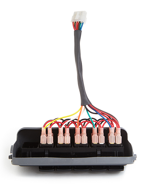
Now it’s time to install the Bussmann RTMR switch harness that you made in Part 5.
This step involves routing the harness from your engine bay, through the firewall, up the A-Pillar and to your overhead console. We will also install the Molex connector that mates with your switch panel.
Parts used in this section:
- Molex Mini-Fit Jr. connector: male, 10-position
- Quantity: 1
- Molex Mini-Fit Jr. terminals: male
- Quantity: 9
- Zip-ties: 6″ length
- Quantity: as needed
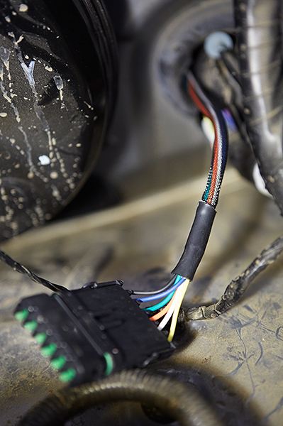
Begin by poking a hole through the firewall grommet in the engine bay. I used a coat hanger and then enlarged it a bit with a utility knife. Be very careful when doing this so that you don’t cut any existing wires traveling through the grommet. If you’re uncomfortable with the utility knife, you could use a small pair of cutters instead.
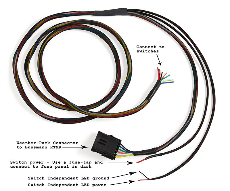
From the engine bay, push the switch harness that you made in Part 5 through the hole in the grommet. Once it’s through a few inches, you can switch to pulling it from inside the vehicle. Continue pulling it all the way through so that only the Weather-Pack connector remains in the engine bay. This means the two pigtails that branch off the harness are now on the inside of the vehicle.
Before routing the wiring harness up the A-Pillar and to your overhead console, we need to install the Molex connector to its end, because it’ll be much easier to do so now. Otherwise, you’ll be working with the harness over your head, and that can be difficult stripping wires and crimping small terminals. Also, leave the two pigtails hanging free under the dash for now. We’ll get to those later.
If you’re not using a Molex connector, you can install your quick disconnects or switchbacks at this point instead.
Begin by stripping all nine wires 3/16″.
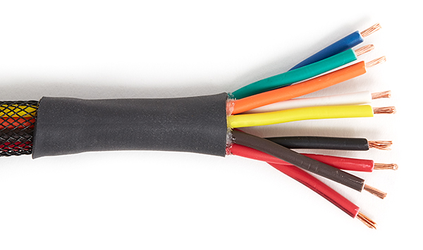
Crimp Molex Mini-Fit Jr. male terminals to each wire.
Insert the terminals into a Molex Mini-Fit Jr. male connector as follows. You need to maintain the position of wires so that it mates correctly with the switch panel connector.
- blue
- green
- orange
- white
- yellow
- ——–
- black
- red
- brown
- red/black
After installing the connector, remove the A-Pillar cover and route the harness up to the headliner. Use zip-ties to secure in place where needed.
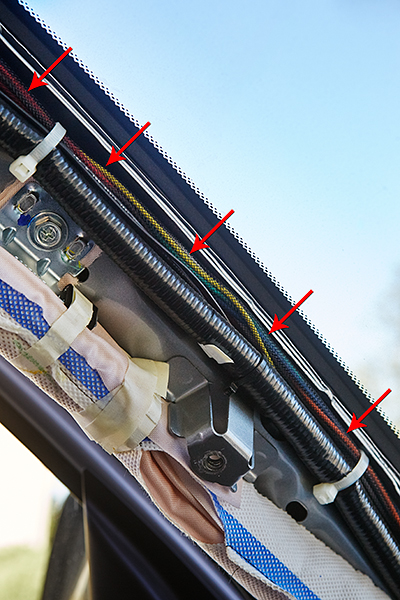
To route the harness under the headliner, I needed to remove the driver-side sun visor. This will allow the harness to easily slip underneath at the windshield. Continue routing the wire harness under the headliner and to the overhead console. The end should be sticking out of the headliner opening where the overhead console goes.
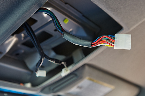
You can re-install the A-Pillar cover, driver-side visor, and overhead console at this point. The wiring harness should still be accessible.
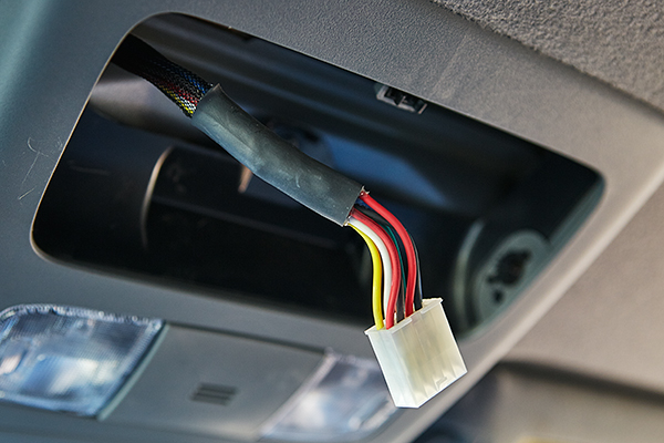
Finally, connect the Molex connectors together and install the sun-glass holder. You may need to push the connectors and slack under the headliner before installing the sun-glass holder.
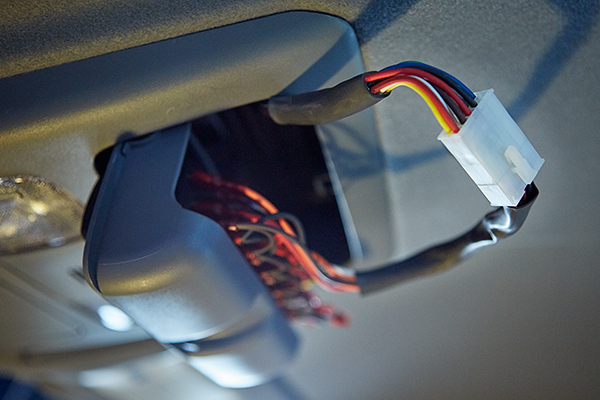
As outlined earlier, closing the sun-glass holder with the switch panel will be a tight fit. The removal of a large portion of the backside of the console should help, but installation can be made to work with a little massaging. I needed to bend the terminals slightly on the back of the switches. When closed, it should look like this.
Electrical Connections
The remaining steps inside the vehicle are to connect power and ground sources for the switch panel.
Parts used in this section:
- Fuse tap: ATM Add-A-Fuse
- Quantity: 1
- T-Tap Wire splice: 22-18 AWG
- Quantity: 2
- Quick Disconnects: 22-18 AWG, male
- Quantity: 2
- Fuse: ATM mini, low-profile 5A
- Quantity: 1
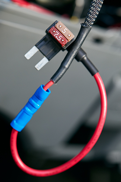
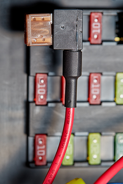
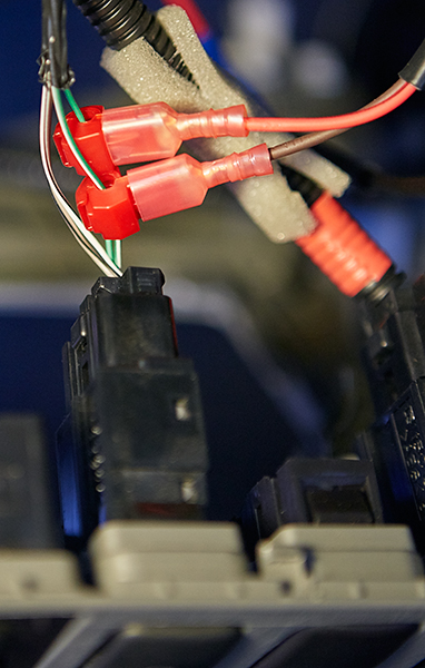
Looking at the pigtails that branch off your switch wiring harness that you installed earlier through your firewall grommet, route the pigtail with the single red wire to your under dash fuse panel. Using a fuse-tap, crimp it to single red wire. Choose an appropriate circuit on the fuse panel such as your 12V accessory outlets. Remove the fuse, and insert it into the primary slot of the fuse-tap. Insert a 5A fuse into the secondary slot. Notice the fuse positions in the following picture.
I cannot guarantee that all fuse-taps will be wired the same, so you can confirm the positions by inserting the original fuse into one slot and using a multi-meter or testing in circuit.
To complete, plug the fuse-tap into the fuse panel.
The other pigtail with the brown and red/black wires will supply power and ground to the lower independent LED of the switches, which will be dimmable. The brightness of the LEDs will be controlled via your dash brightness control, but these wires are not connected directly to the rheostat. Instead, we will tap off of an existing switch in the dash. For example, the VSC Switch is a good choice. Other options would be the Fog Lamp Switch, Downhill Assist Control Switch, or the Differential Lock Switch. Basically any switch lamp that is controlled via the dash light rheostat will work for our needs.
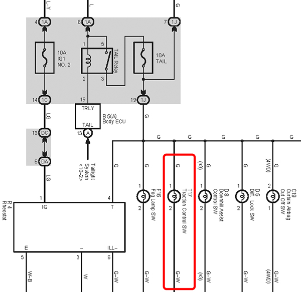
Take a look at the following schematic, which is a small section from the illumination schematic for the 2015 Toyota Tacoma Illumination. You’ll notice that each switch lamp has a green and green/white wire connected to it, which are indicated as “G” and “G-W” respectively. I’ve also circled in red the specific switch that I’ll be tapping into, which is the VSC switch.
If you remember from earlier, the switches are wired with two different grounds. One ground is for the upper dependent LED, which terminates at the Bussmann RTMR. The second ground is for the lower independent LED. The reason we need two different grounds is because of how the dash dimming circuit works. Let me explain.
One might think that the brightness of the dash lights are changed by varying the applied positive voltage to the lamps with ground remaining at 0V. If so, then lowering the positive voltage would result in a lower potential difference between ground and positive, thus resulting in a dimmer bulb. But this would be incorrect. Although the principle is the same, the approach is opposite. By varying the ground voltage instead of the positive voltage, the potential difference between the two changes similarly, and that’s what makes the bulbs dimmer. Think of it this way: the positive source will remain at 12V and the ground is capable of changing from 0V to 12V. With the positive source at 12V and ground at 0V, the difference is 12V, and the bulb is at it’s brightest. With the positive source at 12V and ground at 12V, the difference is 0V and the bulb is off. With the ground voltage level anywhere in between, the difference between positive and ground is what defines the bulbs brightness level.
Hopefully that gives you some understanding of how the circuit works and the confidence to splice into the vehicles OEM wiring. I’ll be splicing into the green and green/white wires for the VSC Switch.
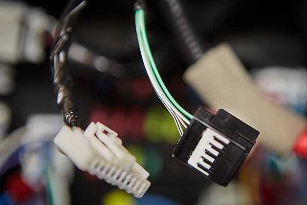
Start be disassembling the dash as necessary to access the switch. Unplug the connector from the rear and remove any electrical tape or sleeving to expose the wires.
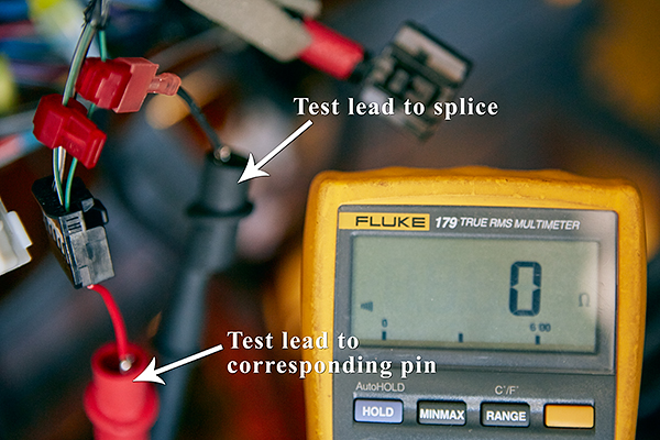
Use two T-Tap Wire Splice connectors to splice into the green power and green/white ground wires. To ensure you have a good connection, a multi-meter can be used to test conductivity between the splice and its corresponding pin.
Route your wiring harness pigtail with the red/black and brown wires to this switch. Strip and crimp insulated male quick disconnects to the pigtail wires. Then install onto the wire-taps. Connect the red/black wire to the green wire for a 12v power source, and connect the brown wire to the green/white wire to supply ground. Complete by plugging the connector back into the switch and reassembling the dash.
Final installation
There are only a few remaining items that we need to do before this project and tutorial are complete. As you know from Part 5, we used Metri-Pack connectors for all accessories, which are waterproof. However, if you leave them hanging off the back of the Bussmann exposed to the elements, they’re not sealed and will be susceptible to corrosion and possibly a short circuit. But with an accessory connected, that circuit is protected and waterproof. For the remaining unused circuits, we need to protect them, and this is easily accomplished.
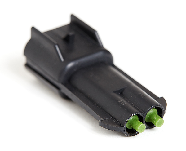
Simply insert cavity plugs into the ends of the mating connector.
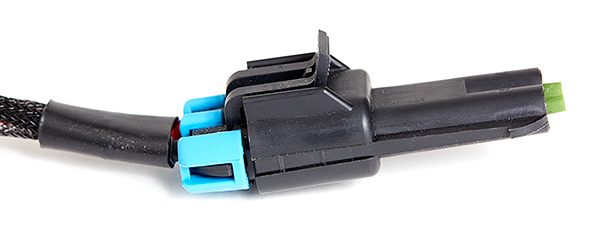
Then plug it in to an accessory cable on the back of the Bussmann RTMR. Do this for each unused circuit and they’re protected..
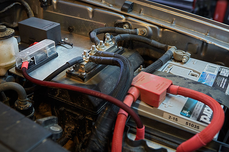
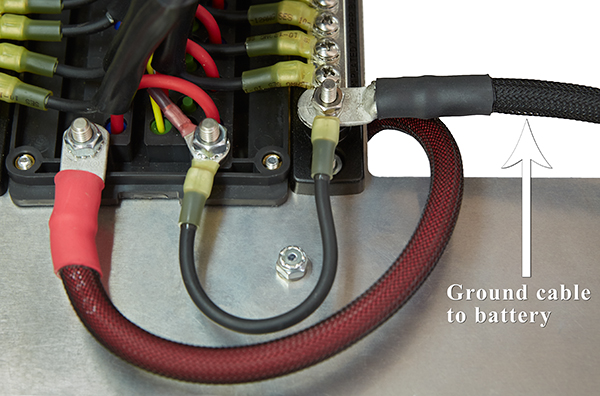
Next, we need to make 4AWG power and ground cables. The length is determined by your battery location and specific setup. Just make sure you use adhesive-lined heat shrink tubing to seal the lugs to the cable. Assemble a red power cable to connect the battery’s positive post to the input side of the ANL fuse. Then make a black ground cable to connect the battery’s negative post to the 2nd external busbar under the bracket. Part 5 indicated exactly where this connection was made, but here’s the location once again as a reminder.
Once these cables are made, you can install the Bussmann RTMR. Locate and drill holes in the bracket, connect the six-way Weather-pack connectors, and install the Bussmann RTMR in your vehicle.
Installation is now complete, and you can safely install accessories that connect to your Bussmann RTMR as needed.
Conclusion
This tutorial has been a long journey. If you made it this far and you successfully built and installed a Bussmann RTMR in your vehicle, congratulations! Not only are you rewarded with a successful installation, you learned what tools and parts are needed to build a Bussmann RTMR, and you learned how to assemble and install the enclosure. You also gained some theory and basic knowledge of electricity regarding switches, relays, wire gauge, etc. Consider all of this valuable information, because if you’re ever out on a trail and are having some sort of electrical issue with your accessories, you should now be confident and skilled in solving the problem.