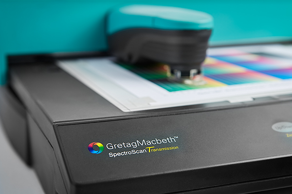
I own a GretagMacbeth SpectroScan T x/y table that is used to read and measure test charts used in the creation of ICC printer profiles. I bought this unit used about eight years ago, and it has served me well throughout this time. However, I recently tried to read a target with the SpectroScan to create a new printer profile, and the device failed and returned an error. In this article, I’ll show you how I problem-solved and ultimately fixed it.
GretagMacbeth manufactured two different SpectroScan x/y tables, one with transmission capability and one without. The one I have is capable of measuring transmissive readings and is designated as SpectroScan T (note the capitol letter T for transmission). Throughout this article, I will shorten the name and simply use SpectroScan to reference my device.
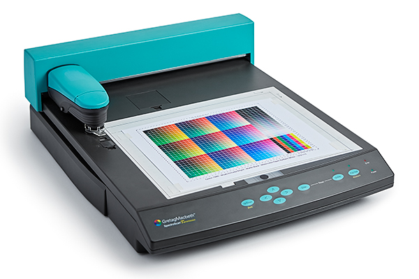
If you’re not familiar with the SpectroScan x/y table, then allow me to explain. In simple terms, it is a device that controls a spectrophotometer, which in this case is a SpectroLino spectrophotometer. The SpectroScan is called an x/y table because it’s able to position the SpectroLino in both the x and y axes. It also tilts the SpectroLino up and down as it maneuvers and takes measurements. Finally, the SpectroScan communicates with software on a computer over a serial line by receiving and sending commands between the computer and the SpectroLino, thereby telling the SpectroLino to take a measurement of a specific color patch on a test chart and send that result back to the computer. A typical chart will take about an hour to measure.
The software I use in conjunction with the SpectroScan is ProfileMaker 5. This is actually a suite of applications which include ProfileMaker, MeasureTool, ProfileEditor, and ColorPicker. Although this package is no longer available, it is still considered a very powerful suite of applications that many photographers continue to use today.

Within the suite of applications, I specifically use MeasureTool with my SpectroScan. This application communicates with the SpectroScan, collects the measurement readings, and saves them to a file that is ultimately used with ProfileMaker to create a printer profile. MeasureTool is rather straight-forward and something that I’ve successfully used in the past on many occasions.

The computer I use with ProfileMaker and the SpectroScan is running Windows XP, and serial communication is through a Keyspan serial-to-USB adapter (P/N USA-19HS). At one point, this was the latest operating system that ProfileMaker would run on due to the HASP authorization dongle not having a compatible driver with newer operating systems. This is no longer the case as a new driver is now available for Windows 7, so I can install ProfileMaker on just about any computer. Furthermore, if I had an Apple computer, that would be another option as well.
THE PROBLEM
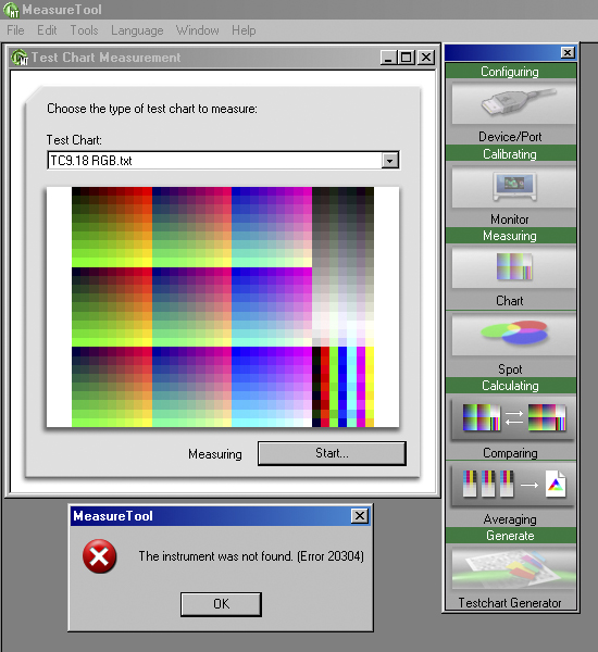
When I attempted to read a target recently, MeasureTool gave me an error: “The instrument was not found. (Error 20304)“. Although I’ve received this error message in the past, I’ve always been able to overcome it by rebooting the device and making sure I was connected properly. Therefore, I took the following steps to troubleshoot my problem:
- Tried two different Keyspan serial-to-USB adapters.
- Tried several different USB cables.
- Tried multiple USB ports.
- Tried combinations of the above on two different computers, Windows XP and Windows 7.
- Tested continuity of each circuit on the 25pin-to-9pin cable(36.50.55). All were good.
- Tried resetting the SpectroLino as outlined on page 17 of the User Guide.
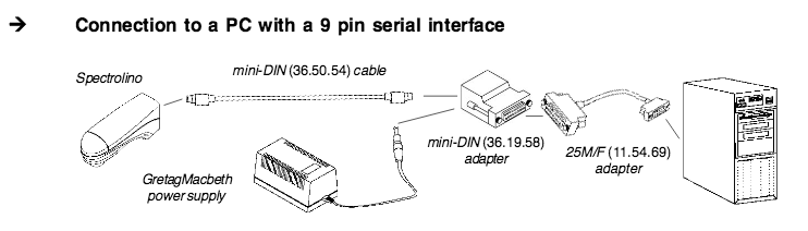
None of the above changes had any affect in resolving the problem. So I called a fellow photographer who owns the same machine and asked if I could borrow his SpectroLino to try on my SpectroScan. Unfortunately, with a different SpectroLino attached to the table, my problem still wasn’t resolved. At this point I began thinking that the issue was with the SpectroScan table and not the SpectroLino, but I wanted confirmation that my SpectroLino was working. To do so, I connected the SpectroLino directly to the computer with the necessary cabling and hardware: a mini-DIN cable (36.50.54), a Gretag external power supply, a mini-DIN adapter (36.19.58), a 25pin-to-9pin cable, and a Keyspan Serial-to-USB adapter. The diagram below from the User Guide shows the setup. The only difference is that a Keyspan adapter was inserted between the last cable and the computer.
Voila! It worked, and I was able to successfully reset the SpectroLino, connect with MeasureTool, and take a spot reading. Therefore, I conclusively confirmed that my SpectroLino was functional and that the problem was definitely with the SpectroScan table and not the SpectroLino.
SEEKING REPAIR
I had gotten to a point where there was nothing else I could do to solve the problem, and I felt that I needed to get the device repaired. GretagMacbeth, however, no longer provided support. In fact, they are no longer around because they were purchased and taken over by X-Rite many years ago, who also no longer supports the SpectroScan. What I’ve learned, though, is repair services for these old devices in the United States was once available through Ernst Hohmann at Automation Engineering, who X-Rite supposedly contracted with. Indeed, I actually spoke with him many years ago regarding another issue with my SpectroScan. But when I tried to reach out to him regarding my current problem, his contact info was a dead end, and I haven’t been able to locate him. So I suspect that he’s either moved or no longer offers his repair services. Either way, I was unaware of any repair company to help me, so I was forced to attempt the repair myself.
When trying to repair electrical equipment, it’s always best to have a schematic and a service manual. However, after searching the internet for as long as I could handle, I was still empty-handed. I knew it was a long shot, but I reached out to tech support at X-Rite and inquired about getting the necessary documents. Although polite, the individual I was conversing with claimed that X-Rite no longer supported or serviced these units and that a schematic or service manual was unavailable. No surprise there. He did say, however, that he would contact a colleague in the UK that may be of help. After a week of waiting, nothing ever materialized, so I was definitely on my own in solving the problem, and disadvantaged at that. But hey! What did I have to lose? The SpectroScan wasn’t working, so it wasn’t like I was going to be any worse off as I tore it apart to investigate. With that said, a level of pragmatism was necessary, so I put haste aside and approached the problem systematically. Let me describe the issue in more detail.
SYMPTOMS AND OBSERVATIONS
Powering Up
When first powering up the SpectroScan, beeps were not emitted from the SpectroLino, which is abnormal behavior. The standard startup procedure when applying power to the SpectroLino is to emit beeps, indicating a power on OK status. This is true when the SpectroLino is connected directly to a computer or via the SpectroScan. Either way, no beeps indicates a problem.
After this, the next step is for the SpectroLino to move to home base over the calibration tile. In my case, this occurred and appeared normal.
Software
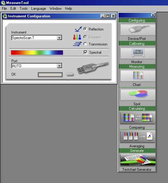
Within MeasureTool, the first step is to configure the Device and Port. This entails selecting the SpectroScan instrument from a drop-down list and choosing the communications Port. I use AUTO for the port, which has always worked fine. When I choose these settings, the status is returned as OK.
Next, I select Measuring Chart to begin scanning a target. After choosing the correct Test Chart, I click the Start button to begin the process. Immediately, the SpectroScan jumps into action and moves the SpectroLino to home base over the calibration tile. This is normal behavior and expected. However, this is where the process stops and after a short while a pop-up window displays: “The instrument was not found. (Error 20304)“.
HYPOTHESIS
With the symptoms and observations outlined, I was able to detail what worked and what did not work and thereby come up with a hypothesis.
I felt confident that the serial communication between the computer and the SpectroScan was working. This was a two-part deduction. First, MeasureTool was able to communicate with the SpectroScan during Configuration, and the status was indicated as OK. Although I didn’t use a Serial Port Monitor application to actually read the serial port data, the general assumption is that some sort of handshaking must happen to pass this stage. Otherwise, I wouldn’t be able to configure the device within MeasureTool, and the Status would not be indicated as OK. What’s important here is the absence of an error message during configuration.
Secondly, when initiating a Measuring Chart task, the SpectroLino moves to home base over the calibration tile before it fails and produces an error. Therefore, this indicates that commands are sent to the SpectroScan to initiate the process. Otherwise, if serial communication was broken, then nothing would happen when the Start button is clicked.
With this information, I was able to confirm that the serial driver/receiver chip and the main processor chip were functioning correctly. Let me explain. As mentioned earlier, MeasureTool must handshake in some way with the SpectroScan during configuration by sending a command to the SpectroScan, which signals a response to complete the setup. If this is the case, the serial command must be received and decoded by the serial driver/receiver chip before traveling to the main processor. Furthermore, the main processor subsequently sends a command back to the computer alerting of its presence and status, thus establishing a connection.
If you’re still not convinced, think of the actions of the stepper motors thus far, which are the motors used to position the SpectroLino. At this juncture, all three motors were capable of control via the front panel. Additionally, they were set into action when initiating a chart measurement within MeasureTool. Not only were both the x and y axes functional, but so was the tilt mechanism. From this observation, I concluded that the main processor must be working as well as the stepper motor controller chips. Commands to move a particular motor are first sent to the main processor, no matter if they emanate from the serial line or the front panel. Once processed, the command is passed to the stepper motor controller, which then sends a signal to a specific motor to move in one direction or another.
In summary up to this point, serial communications was functional as was the serial driver/receiver, main processor, and stepper motor chips. I also concluded that the stepper motor limit stops were functioning as well. There is a total of three, one for each motor. When the SpectroLino correctly positioned itself over the calibration tile and tilted accordingly, it told me that the limit stops were able to communicate an electrical signal back to the main processor, which subsequently told the motors to stop or move.
All of this information was valuable to me when trying to solve the problem. It gave me a starting point as to what the actual problem was and where to look. I also thought about the original error code: “The instrument was not found. (Error 20304)“. This implied that the SpectroLino could not be found, as if it wasn’t even plugged in. Therefore, I was beginning to hypothesize that I had either a power or communications issue between the main circuit board and the SpectroLino. It was time to take the unit apart and see if I could locate the problem.
INSPECTION
When opening the SpectroScan for the first time, I was impressed at how simple it is.
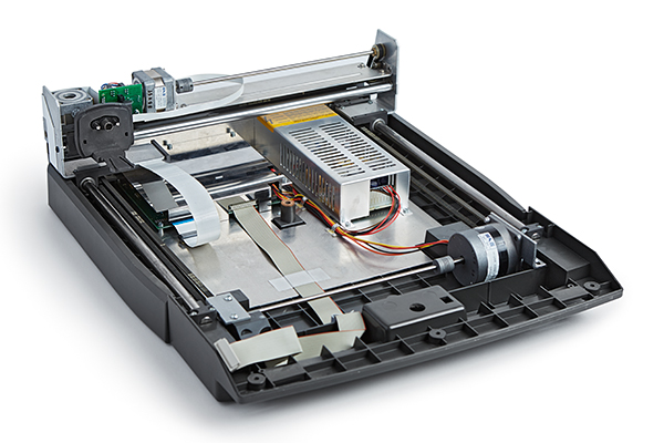
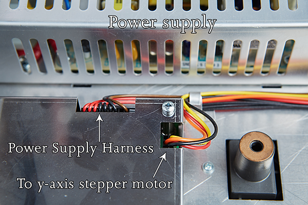
The power supply is a standalone unit.
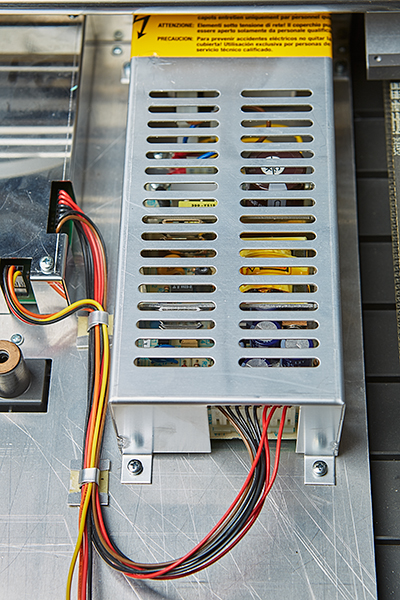
The power supply wiring harness is a total of seven wires, which connects to the main board. Power is distributed to the stepper motors, front panel circuit board and the SpectroLino from the main circuit board through various other cabling.
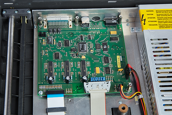
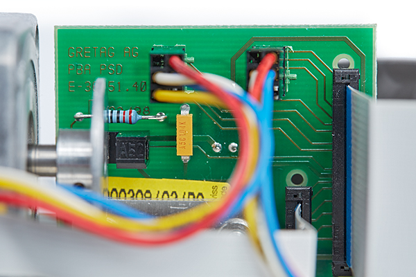
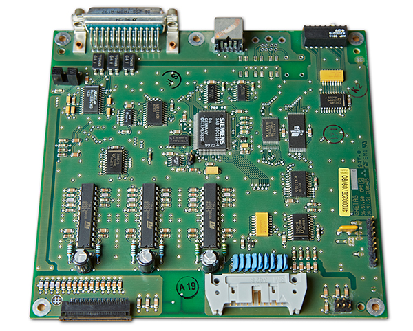
The main circuit board hosts a Siemens 80C166 micro-controller, Maxim MAX238CWG RS-232 driver/receiver chip, ST L6219 stepper motor driver chips, AT29C010A flash memory, TC55257DFTL SRAM memory, and several other miscellaneous chips.
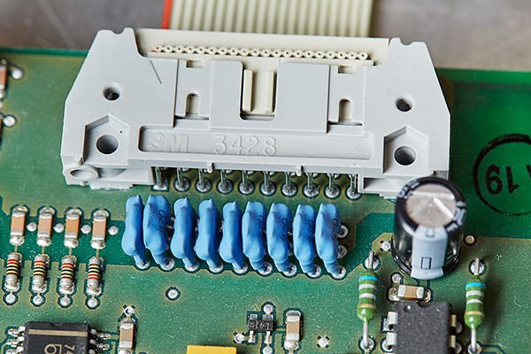
Communication to the front panel is through a 20-pin ribbon cable.
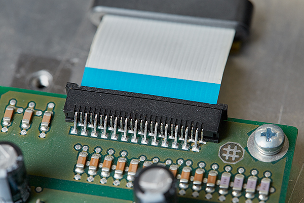
Communication to the SpectroLino and the two other stepper motors is through a 26-pin flat flex cable.
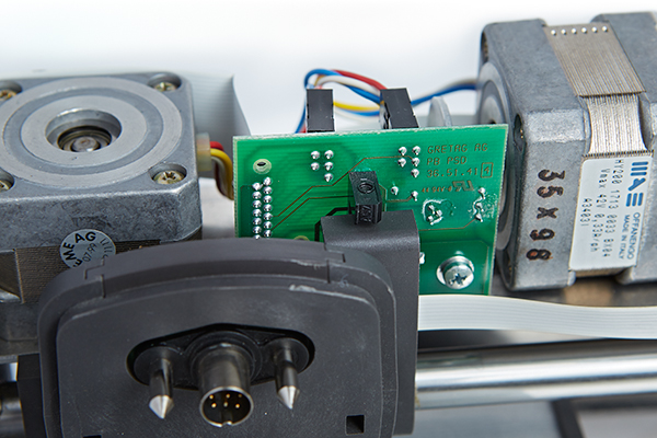
An intermediate circuit board serves as a central connection point for two stepper motors, their limit stops, and another connector for an 8-pin flat flex cable that connects to a third circuit board.
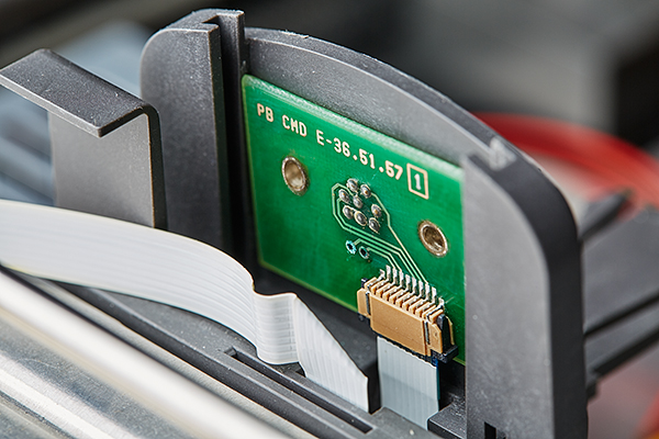
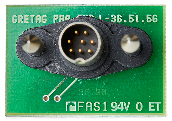
This small board is nothing more than a way to mount and connect the SpectroLino. It doesn’t contain any components other than the 8-pin flat flex cable connector and the mini-DIN connector.
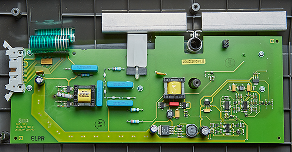
The front control panel circuit board mounts underneath the top surface of the SpectroScan table:
With the SpectroScan opened, I wanted to do some preliminary testing before digging deeper, so I checked the power supply. Although I didn’t suspect there would be a problem, this is standard procedure when trouble-shooting electronics. I actually learned this lesson many years ago in high school with a Commodore 64 computer that was malfunctioning. I brought the computer into my electronics class to try and repair the garbled display. After my teacher and I worked on it for weeks, we eventually gave up. It wasn’t until I got a new replacement computer that I had the idea of trying the new power supply on the old computer. And what do you know? It worked! When I told my teacher, I think he felt a little foolish.
Anyway, with my SpectroScan, the power supply wiring harness had seven wires: three black ground wires, three red supply wires, and a brown supply wire. Using a multimeter, I measured 23.98v on each red wire and 4.994v on the brown wire. Without a schematic telling me what they’re supposed to be, these values appeared normal to me, so I assumed they were correct.
Next, I found a PDF file on X-Rite’s website outlining the serial interface of the SpectroScan and SpectroLino: SpectroLino SpectroScan SERIAL INTERFACE Edition 5. Although it referenced an older version of each, I assumed some of the information must still apply. What I was looking for most specifically was the pin configuration of the SpectroLino, which I found on page 72:
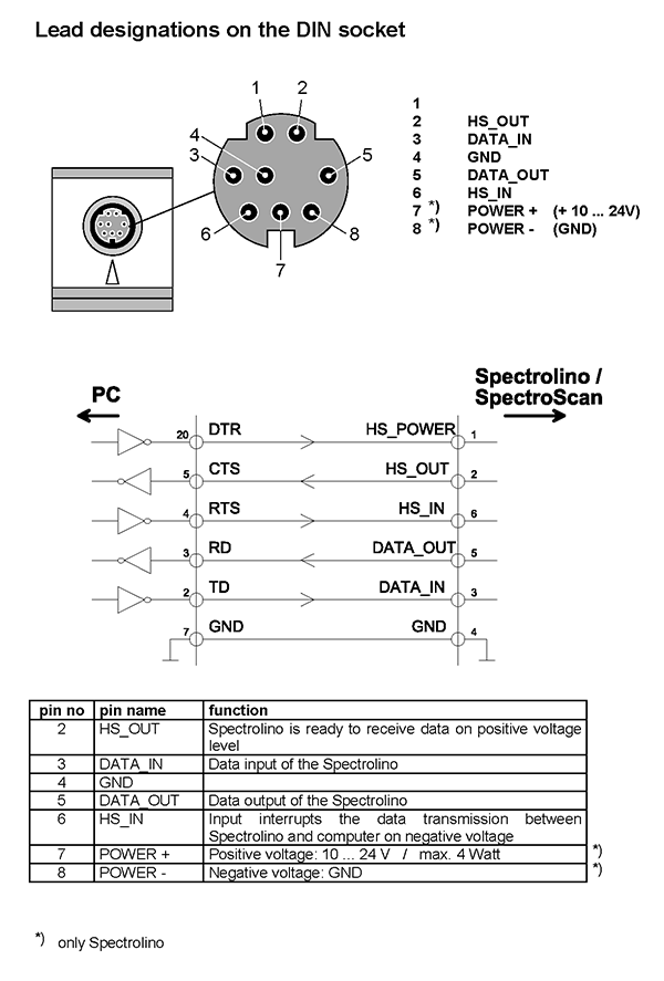
With this information, I knew each pins designation, which allowed me to measure for power at the mini-DIN connector that the SpectroLino plugs into. When doing so, I measured 23.90v on pin 7 with pin 4 as ground. This was looking good, and I was beginning to think that the problem wasn’t a power issue but a communications one. Perhaps the problem was a faulty flat flex cable preventing communication between the SpectroLino and the main processor.
Two flat flex cables are used for communication from the main circuit board to the SpectroLino: a 26-pin cable connecting the main board to the intermediate board and an 8-pin cable connecting the intermediate board to the small board where the SpectroLino plugs into. After testing the cables, the good news was that each circuit on both cables tested good for continuity. The bad news was that the flat flex cables were not the problem.
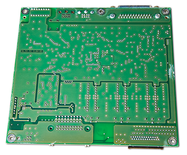
Digging a little deeper, I removed the main, intermediate, and small circuit boards to study them more closely.
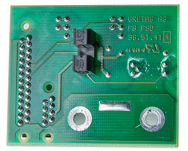
Main board:
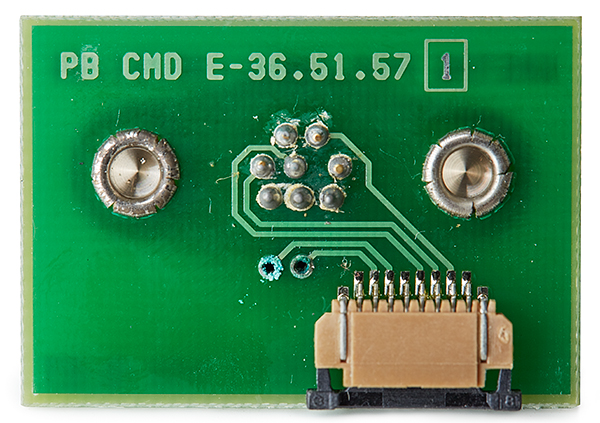
Intermediate board:
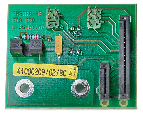
Small board:
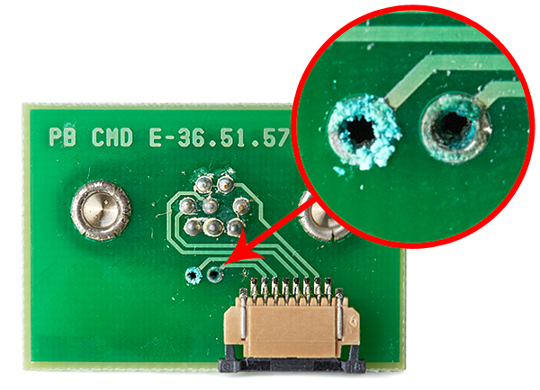
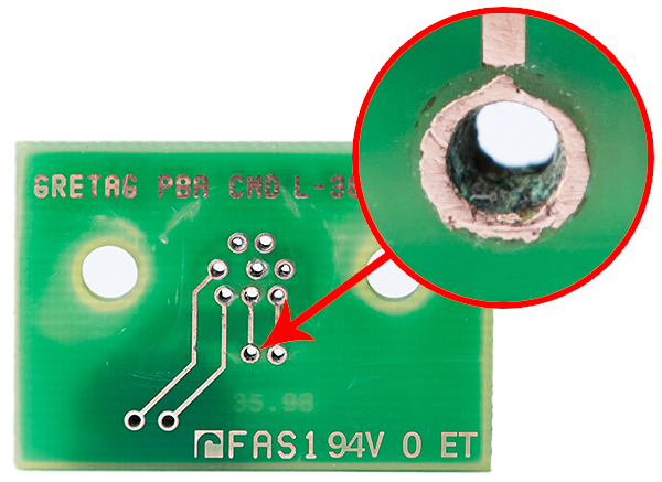
With the boards on the bench where I could inspect them more meticulously, I didn’t see any defective components or obvious signs of damage with the exception of two things. First, the small circuit board that the SpectroLino plugs into had some crusty solder connections on the pins of the mini-DIN connector. These could be potential cold solder joints. Additionally, there was some corrosion at the via holes, which are used to connect traces from one side of the circuit board to the other. I wasn’t certain if either was the culprit, but this circuit board quickly became the main suspect.
REPAIR
With the small circuit board now looking questionable, I thought it best to test the continuity of the mini-DIN connector to the 8-pin flat flex cable connector. Although I had previously measured 24v on pin 7, I surprisingly discovered that I had no continuity on this pin. The remaining pins tested good, so pin 7 was looking like the obvious cause of the malfunction.
If you remember from the SERIAL INTERFACE PDF that I showed you earlier, the pin designations specified pin 7 as a power source to the SpectroLino. Therefore, without power to the SpectroLino, it wouldn’t be able to reset or communicate. It effectively becomes non-functional, and as far as the SpectroScan and MeasureTool are concerned, it acts like it’s not plugged in, exactly as the error code indicated: “The instrument was not found. (Error 20304)“.
What I thought odd, however, was that I had previously measured 23.90v on this pin. So what does this mean? All I can surmise is that corrosion or a broken trace with a slight or intermittent continuity might be capable of measuring the potential force of a power supply, yet is unable to sustain a current demand. Whatever the case, I was now acutely focused on this circuit as the root of my problem.
Suspecting corrosion as the cause, I doused the board with DeoxIT and scrubbed it clean. Unfortunately, the problem remained, even after letting it soak overnight. Therefore, I removed the mini-DIN connector and cleaned up the board further to see if I could find the reason why the connection was broken. I immediately identified the problem. As the photo shows below, the reason why I did not have continuity between pin 7 of the mini-DIN connector and the flat flex connector was because of a broken trace. The location on the circuit board was underneath the black housing of the mini-DIN connector, so there was no way to see it without removing the connector.
My initial attempt to fix the broken trace was to bridge the gap with solder, but when doing so, the trace lifted off of the board and prevented me from fixing it with this technique. Therefore, I needed a different solution. If I had had a silver conductive pen on hand, that probably would have worked, but without one, I opted to install a bodge wire instead. This is simply a jumper wire from one point to another.
After re-installing the mini-DIN connector, I soldered a jumper wire on the back side of the board as shown below. This bodge wire directly connects pin 7 of the mini-DIN connector to the trace that continues to pin 7 of the flat flex cable connector.
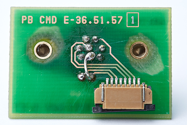
This is not the most elegant way to fix a problem. But hey! It got the job done and returned continuity between pin 7 of each connector. Afterwards, I ensured that continuity of the remaining pins was accurate and that I did not induce any cross-talk between circuits. With this fix in place, I was confident that my original problem had been solved, so I didn’t feel the need to do any further testing. It was time to re-install the board into the SpectroScan and test.
SUCCESS
Immediately upon power up, I knew I had fixed the SpectroScan when a series of beeps were emitted from the SpectroLino and it moved itself over the calibration tile. I was excited and couldn’t open MeasureTool fast enough to test. As expected, the SpectroScan configured correctly, communication was established, and I was able to initiate a chart measurement without any errors. Whoo-hoo! An hour later, the measurement was complete and ready to make a printer profile in ProfileMaker. I solved the problem!