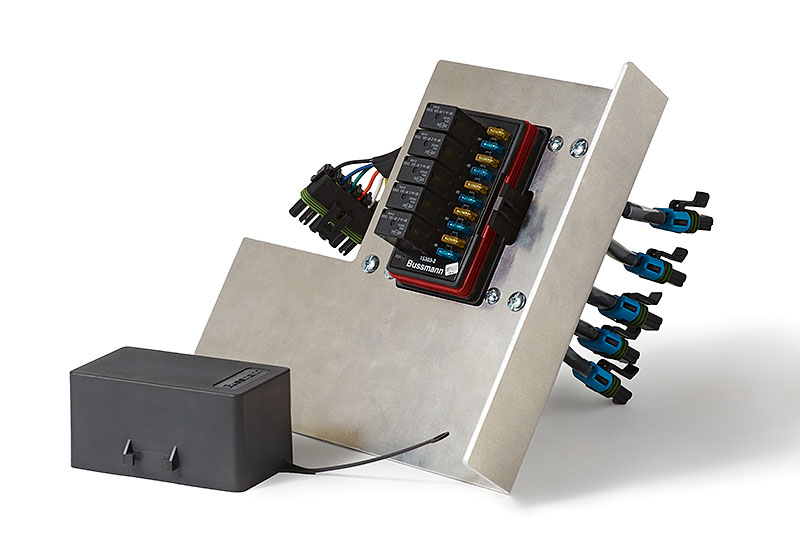
This is Part 5 in an on-going series of tutorials that will teach you how to build a Bussmann RTMR fuse/relay block for your vehicle. We’ve already covered what the Bussmann RTMR fuse/relay block is, what parts are required, what tools are necessary, and techniques to build it. In this part, we’re going to put it all together so that you will have a completed Bussmann RTMR fuse/relay block that you can install in your vehicle.
There are several steps involved in putting this enclosure together.
- Mounting RTMR and ground busbars to bracket
- Insert cavity plugs into unused cavities
- Making the switch harness
- Making jumper cables
- Making accessory cables
- Installing fuses and relays
And as a reminder, I take no responsibility for damage, accidents, or injuries resulting from the fabrication or installation of any electrical modifications to your vehicle. You do so at your own risk.
MOUNTING RTMR AND BUSBARS
This section will simply mount the RTMR and busbars to the bracket.
Parts used in this section:
- Bracket: Standard Large Mounting Plate with kick-out by Yotamac
- Quantity: 1
- Busbars: Blue Sea Systems 5 Gang Common 100A Mini Busbars, part #2304
- Quantity: 2
- Screws: 10-32
- Quantity: 4
- Screws: 10-24
- Quantity: 4
- Nuts: 10-24
- Quantity: 4
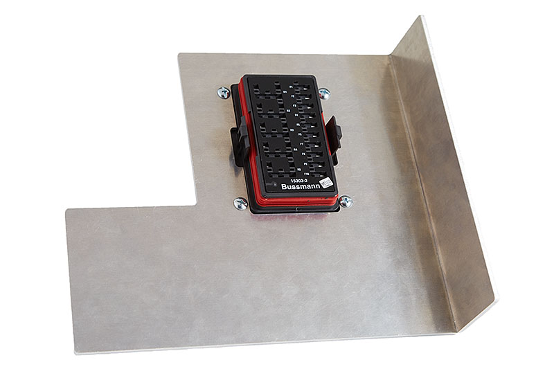
Let’s begin by installing the RTMR enclosure to the bracket. This is simply done by screwing it into place. The RTMR is inserted from the bottom of the bracket with four 10-32 screws affixing it in place.
Next, we want to mount the two ground busbars. One busbar will be used as the ground bus for the five accessories connected through the relays while the other will be used as the ground bus for the five accessories connected solely through the fuses. I’m using Blue Sea Common 100A Mini busbars. This is a good size, because it’s current rating is slightly higher than the internal busses of the RTMR. Each bus within the RTMR is rated at 80 amps. Additionally, it has five #8-32 screw terminals along with two #10-32 studs. This is a perfect number of attachments for the accessory grounds as well as the primary ground wire to the battery. Last, the physical size and spacing just happens to work out perfectly as you’ll see.
To mount the busbars, I aligned them up on either side of the RTMR, marked the hole locations, drilled holes, and attached with 10-24 screws and nuts. As you can see in the picture, I mounted the busbars with the hardware backwards. Typically, the screw head would be on the side of the busbar with the nut on the backside of the mounting surface. However, to maintain a clean look with only screw heads showing on the top surface of the bracket, I installed the nut into the recessed hole in the busbar instead of the screw. With this particular screw and nut size, the nut wedges into place and prevents it from spinning while tightening. If you use a different screw and nut size or want more reinforcement, you could always add a bit of epoxy on the nuts.
INSERTING CAVITY PLUGS
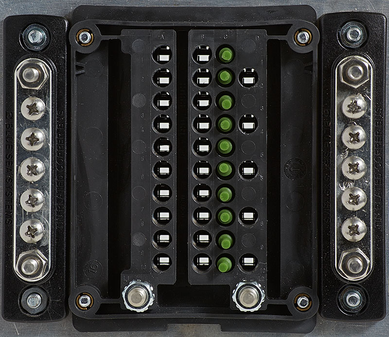
There are a few cavities in the RTMR that won’t be used, which we need to seal from water and contaminants.
Parts used in this section:
- Cavity plugs: Metri-Pack 280 Cavity Plugs – 12010300
- Quantity: 10
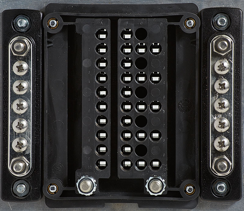
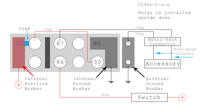
If you remember from Part 4 – Wiring and Schematics, we’re using 4-pin relays. As a result, all of the cavities associated with pin 87A on a 5-pin relay need to be sealed with cavity plugs. When looking at the RTMR from the back, this is the entire middle row of cavities on the right side. Simply insert a Metri-Pack 280 green cavity plug into each of these holes.
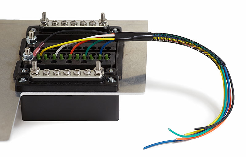
MAKING SWITCH HARNESS – PART 1
The switch wiring harness is composed of two parts. The shorter part is permanently connected to the RTMR with a Weatherpack connector on the end. The second part has the mating connector and is the longer harness that travels through the firewall to your switches.
Let’s begin by making the shorter switch wiring harness that connects to the RTMR. We need to make this now, because these wires will be inserted into the RTMR before any subsequent wiring, which are installed over the top. They are also 18 AWG wire and can be a bit temperamental when installing. So it just happens to be easier to insert them without any other wires in the way.
The switch harness is composed of six wires. Five circuits are the positive signals from the switches and the sixth is a ground wire for the switch independent LEDs. With six wires in total that need to be passed through the vehicle’s firewall, you have the option of hard-wiring or using a connector. I prefer using a connector so that I can easily remove the entire bracket and RTMR in the future for any reason. Therefore, a Weather-Pack six-way connector is a perfect solution. It’s waterproof, chemical resistant, and the exact size needed.
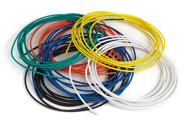
With multiple circuits, it makes sense to vary the color of each wire. Therefore, I’ll use a different color, excluding red or black, for each of the five circuits. I’ll then add a black ground wire for the switch independent LEDs. The color sequence of the circuits can be in any order that you choose, but I’ve always found that it makes logical sense to alphabetize the colors corresponding to numerical ordering of circuits. This helps me to troubleshoot in the future. Therefore, I’ll be using this specific ordering of wires: black, blue, green, orange, white, yellow.
Now let’s get down to business and make something. The parts I’m specifically using in this step are the following:
- Connector: Weather-Pack Six-Way Female – 12015799
- Quantity: 1
- Terminals for connector: Weather-Pack Female 20-18 AWG – 12089188
- Quantity: 6
- Terminals for RTMR: Metri-Pack 280 Sealed Tangless Female 18-16 AWG – 12110847
- Quantity: 5
- Cable seals: Metri-Pack 280, Green 20-18 AWG – 12015323 / 15324982
- Quantity: 11
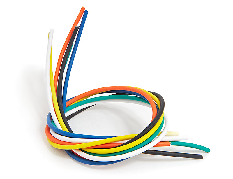
- Wire: 18 AWG GXL
- Colors: black, blue, green, orange, white, yellow
- Quantity: 13″ each color
- Ring Terminals: 20-18 AWG heat shrink, 1/4″ hole
- Quantity: 1
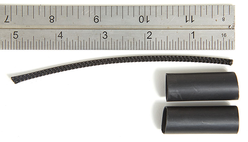
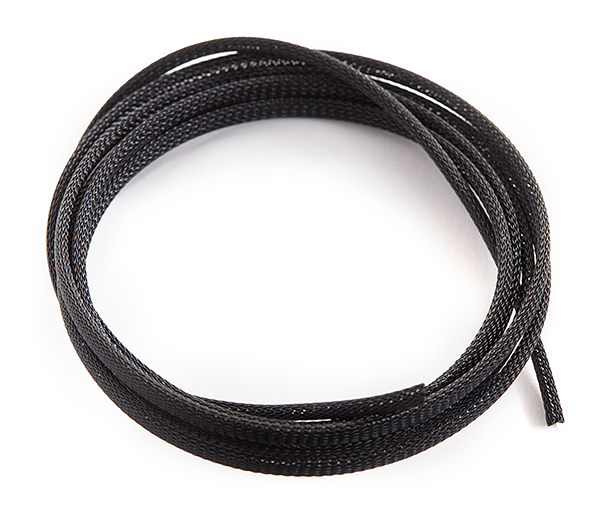
- Wire loom: 1/4″ expandable braided sleeving
- Quantity: 5″
- Heat shrink: 1/2″ adhesive-lined
- Quantity: 3″
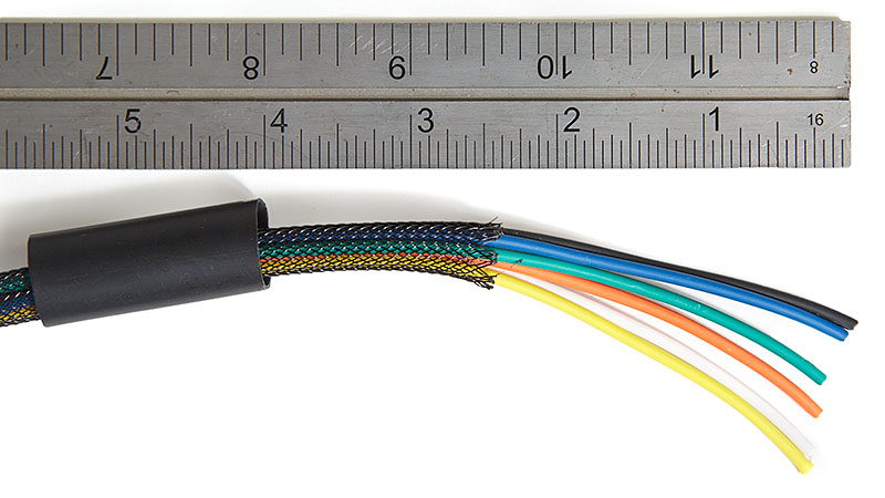
Start by cutting one black and five different colored 18 AWG GXL wire, 13″ long.
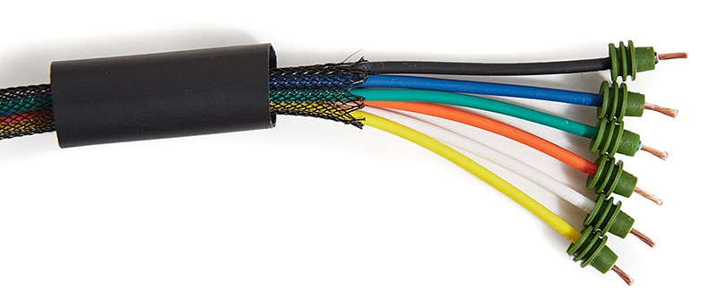
Set the black wire aside and slip on green cable seals to the colored wires. These need to be installed first, because doing so after stripping can be a bit difficult without bending the exposed wire.
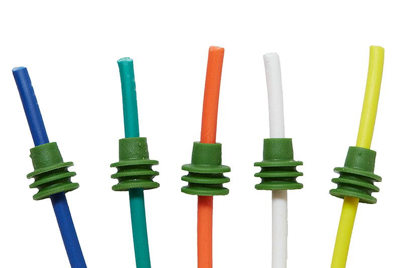
Strip one end of each wire 7/32″ and slide cable seals up into place.
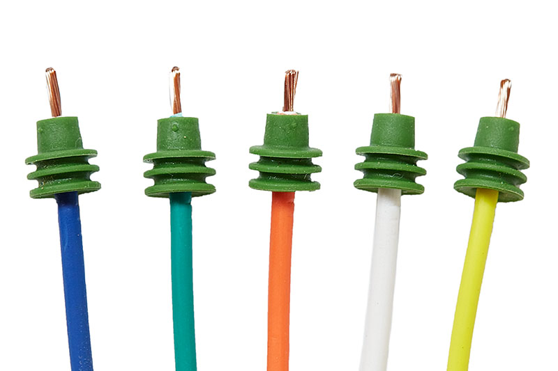
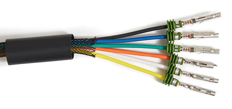
Using the T-18 crimper, crimp Metri-Pack 280 Sealed Tangless Female 18-16 AWG terminals using setting “3”. Then crimp the cable seal using setting “5”.
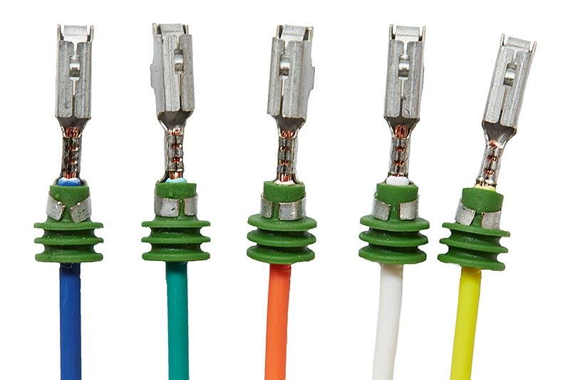
If you choose to solder your terminals, do so now.
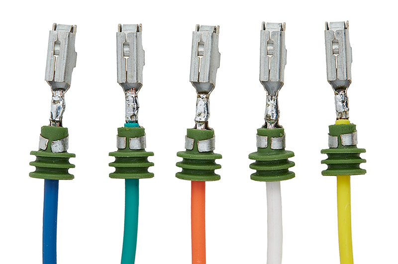
Insert terminals into the Bussmann RTMR to pin 86 for each relay.
These will only insert in one direction. So don’t force the terminal in. If it doesn’t easily insert, then turn it around. I maintained alphabetical ordering of color corresponding to relays one through five.
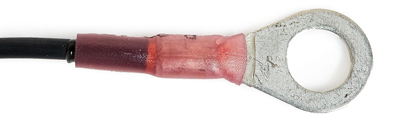
Strip the black wire 1/4″ long, slip on 22-18 AWG heat shrink terminal with 1/4″ hole, and crimp. Use a heat gun to seal.
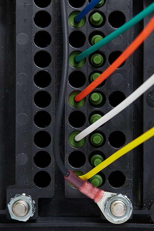
Attach black wire to stud on RTMR for the 2nd internal ground bus. Place the wire as follows.
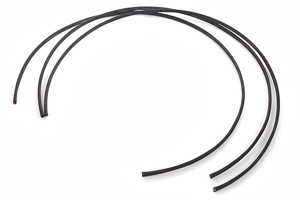
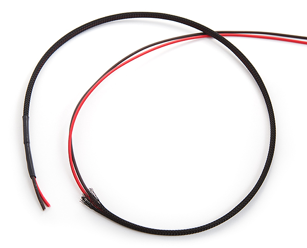
Cut 1/4″ braided sleeving 5″ long and two pieces of 1/2″ diameter heat shrink 1.5″ long. I’m using adhesive-lined heat shrink to help hold everything in place. But this isn’t a requirement, because it’s not sealing any connections.
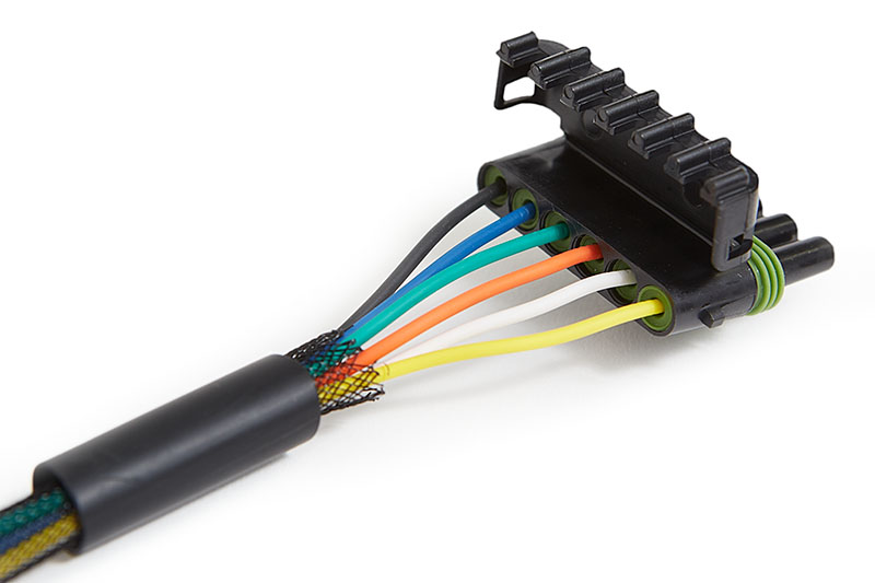
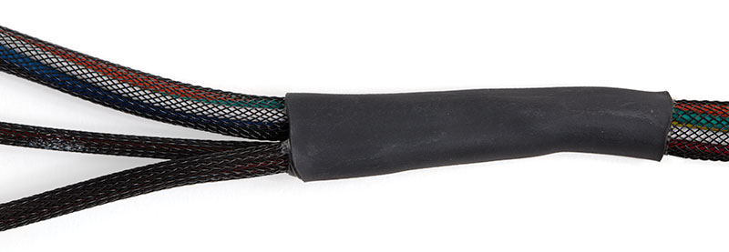
Gather all of the wires towards the top end of the Bussmann RTMR so that they lay flat and grouped together. Slip on braided sleeving and one piece of heat shrink tubing. Align braided sleeving and heat shrink so that they’re up close to the RTMR with the end of the sleeving in the middle of the tubing. Use heat gun to shrink and hold in place.
Cut wires evenly so that they’re 2.5″ away from the end of the sleeving. Slip on second piece of heat shrink tubing, and slide down the harness a bit. Don’t put into place and use a heat gun yet. We want to install the Weather-Pack connector first and then slide the tubing into place afterwards.
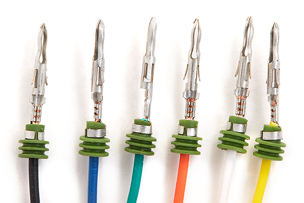
Slip on green cable seals to each wire, strip each wire 7/32″, and slide cable seals into place.
Using the T-18 crimper, crimp Weather-Pack Female 20-18 AWG terminals using setting “3”. Crimp cable seals using setting “5”. If you’re soldering terminals, do so now.
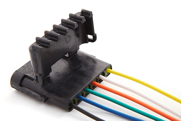
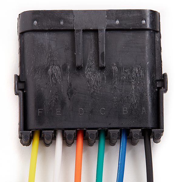
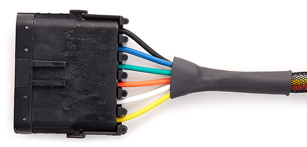
Insert each terminal into Weather-Pack female connector while maintaining correct order of wire colors: black, blue, green, orange, white, yellow. The Weather-Pack connector has labels A-F for each circuit. I started my sequence with “A” as circuit one.
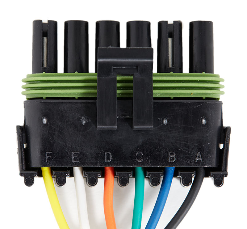
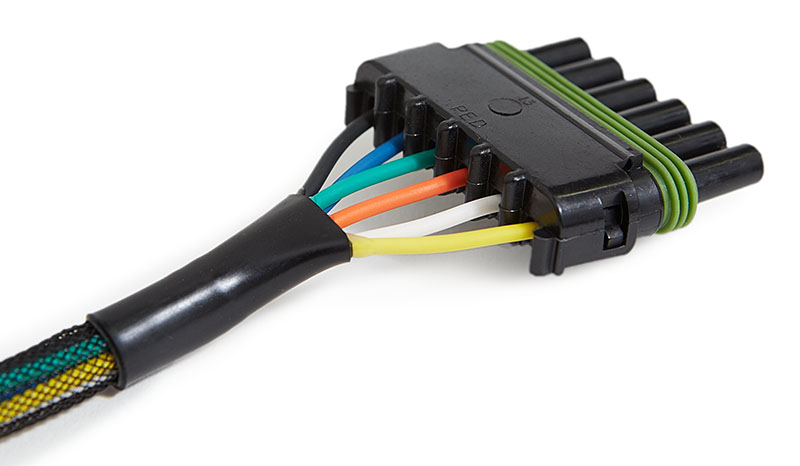
Flip down Terminal Position Assurance latch. This assures that the positioning of the terminals remains within tolerance and will allow the mating connector to align without any problems. Then slide the heat shrink up into place, and use a heat gun to shrink.
MAKING SWITCH HARNESS – PART 2
The second part of the switch wiring harness plugs into the short harness extending from the RTMR, travels through the firewall, and continues to your switches. Additionally, it contains wires for powering the switches and controlling the switches’ independent LED brightness.
 The parts I’m specifically using in this section are as follows:
- Wire: 18 AWG GXL
- Colors: black, blue, green, orange, white, yellow, red, red/black, brown
- Quantity: 90″ each color
- Heat shrink: 3/8″ adhesive-lined
- Quantity: 4″
- Heat shrink: 1/2″ adhesive-lined
- Quantity: 2″
- Heat shrink: 3/4″ adhesive-lined
- Quantity: 2″
- Wire loom: 1/4″ expandable braided sleeving
- Quantity: 151″
- Terminals: Weather-Pack Male 20-18 AWG – 12089040
- Quantity: 6
- Connector: Weather-Pack Six-Way Male – 12010975
- Quantity: 1
- Cable seals: Metri-Pack 280, Green 20-18 AWG – 12015323 / 15324982
- Quantity: 6
This harness contains a total of nine wires:
- Five for the switches
- one for the switches’ ground
- one for switches’ power
- one for switches’ independent LED power
- one for switches’ independent LED ground.
Start by cutting one black and five different colored 18 AWG GXL wire, 90″ long. I used the same colors as before: blue, green, orange, white, and yellow.
Slip on green cable seals to each wire, strip each wire 7/32″, and slide cable seals into place. Using the T-18 crimper, crimp Weather-Pack Male 20-18 AWG terminals using setting “3”, and crimp cable seals using setting “5”. If you’re soldering terminals, do so now.
Insert each terminal into Weather-Pack male connector while maintaining correct order of wire colors: black, blue, green, orange, white, yellow. The Weather-Pack connector has labels A-F for each circuit. I started my sequence with “A” as circuit one.
Flip down Terminal Position Assurance latch. This assures that the positioning of the terminals remains within tolerance and will allow the mating connector to align without any problems.
Cut three pieces of 1/4″ braided sleeving 22″ long.
Set two aside and slide one piece over all wires up to the connector. Cut a 2″ piece of 1/2″ heat shrink tubing and slip over sleeving. Slide into place up near connector while positioning the braided sleeving roughly in the middle of the tubing. Use heat gun to shrink in place.
Cut three more wires at 90″ long. One is for all switches’ power, so I used red. Another is for all switches’ independent LED power, so I used red with a black stripe. And the third is for all switches’ independent LED ground, so I used brown.
Using one of the remaining two pieces of 22″ long 1/4″ sleeving, slide over the red wire. Position so that it’s about 2″ from the end. Cut a 2″ piece of 3/8″ heat shrink tubing, slide over the wire and sleeving. Position so that sleeving is roughly in the middle of the tubing and that 1″ of wire is hanging out. Use a heat gun to shrink in place.
Using the last piece of sleeving, slide over the red/black and brown wires. Position so that it’s about 2″ from the end. Cut a 2″ piece of 3/8″ heat shrink tubing, slide over the wires and sleeving. Position so that sleeving is roughly in the middle of the tubing and that 1″ of wire is hanging out. Use a heat gun to shrink in place.
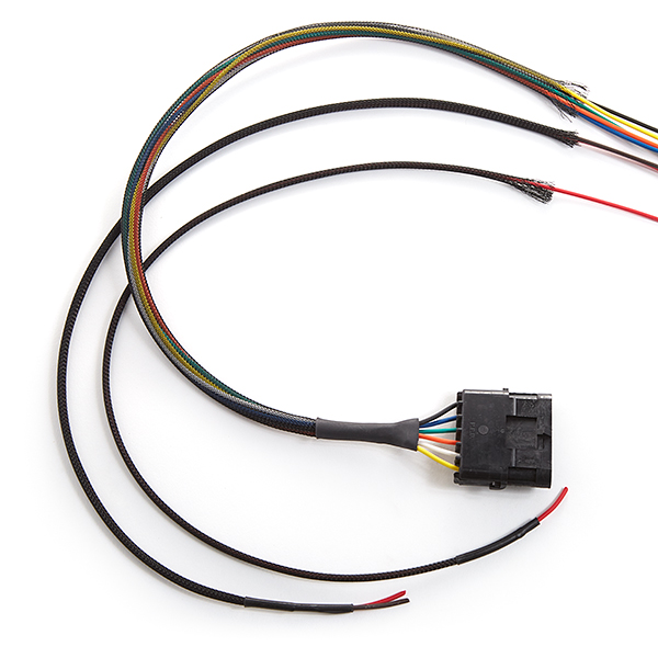
Bundle the three separate wiring harnesses together so that the loose ends are aligned. This will position the wires as shown below. What’s important is that the ends of the braided sleeving in the middle of the wiring are aligned.
Cut an 85″ length of 1/4″ braided sleeving.
Grabbing all nine wires with the ends aligned, slide the braided sleeving over the group, continue until it meets the three shorter sections of braided sleeving.
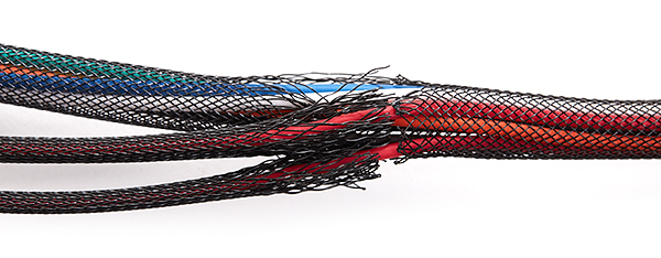
Cut a 2″ piece of 3/4″ tubing. Slide down the wiring harness and position over the the point in the middle where the various sections of braided sleeving meet. Use a heat gun to shrink in place.
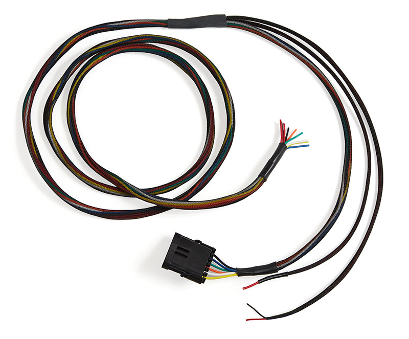
Cut a 2″ piece of 3/4″ heat shrink tubing. Slide over the loose end of all nine wires and position so that the braided sleeving is roughly in the middle. About 2″ of wiring should remain exposed. Trim wiring if necessary. This is what it should look like now.
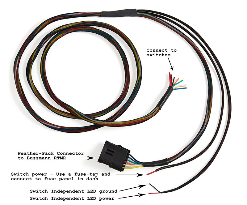
At this point, you can set the switch wiring harness aside. I’ll continue later with more details about how and where to connect the specific wires during Part 6 – Installation. At this point, however, be aware that you don’t want to install any connectors yet to the wire ends. You’ll want to run it through the firewall first and snake it into place.
MAKING JUMPER WIRES
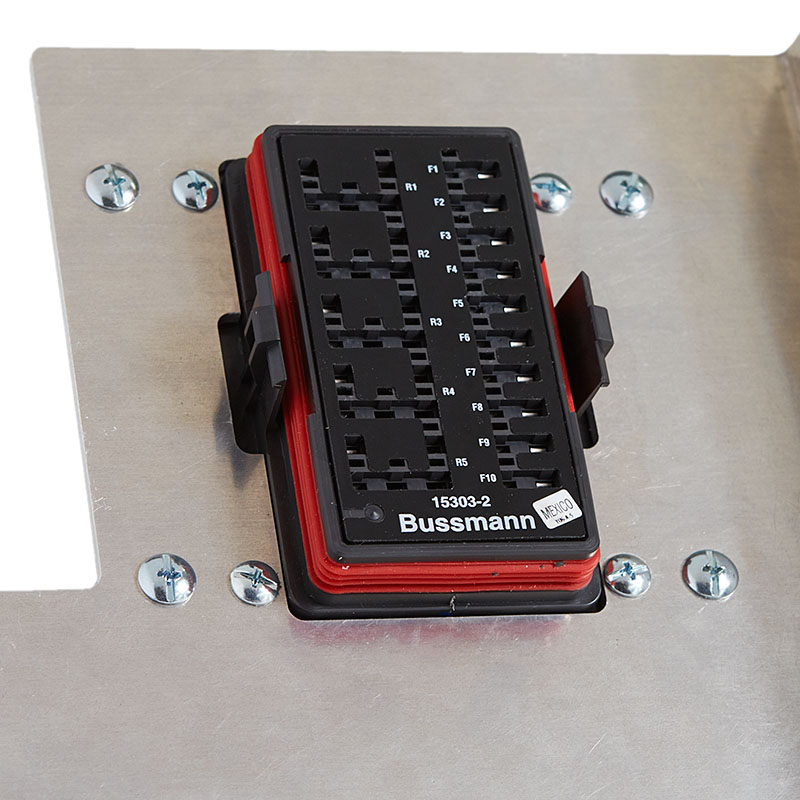
We need to make five jumper wires that connect power from a fuse to pin 30 of the relay. With five relays, we’ll use five fuses. The other five fuses can be used for non-relay, low-power accessories. Now it’s up to you which fuses you want to use in conjunction with the relays. For example, you can use fuses 1-5, 6-10, odd-numbered fuses, even-numbered fuses, or any crazy sequence that you like. Personally, I used odd-numbered fuses with the relays. I chose to do it this way, because the relays take up two rows of cavities in the RTMR, and the odd-numbered fuses align with the first row of each relay. This makes the wiring layout clean and elegant. Ultimately, it doesn’t make a difference.
The parts I’m specifically using in this step are the following:
- Terminals for RTMR: Metri-Pack 280 Sealed Tangless Female 12-10 AWG – 12110853
- Quantity: 10
- Cable seals: Metri-Pack 280, Blue 12 AWG – 12015193 / 15324981
- Quantity: 10
- Wire: 10 AWG TXL
- Colors: red
- Quantity: 17.5″
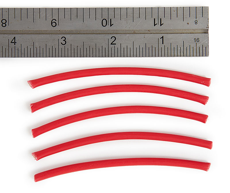
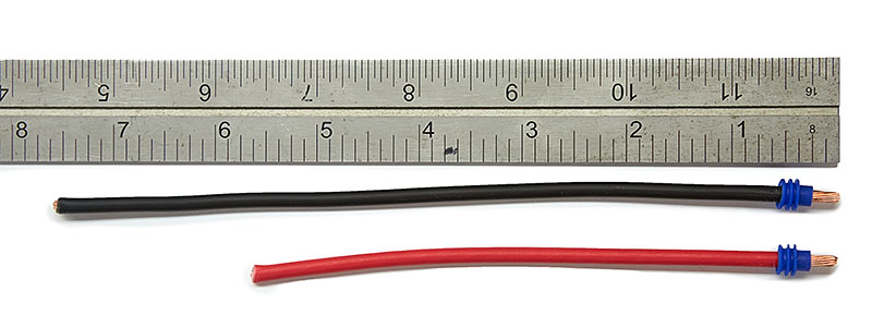
Cut five lengths of 10 AWG red wire 3 1/2″ long.
Slip on blue cable seals to both ends, strip each end 7/32″, and slide seals up into place.

Using the T-11 crimper, crimp Metri-Pack 280 Sealed Tangless Female 12-10 AWG terminals with setting “B” on both ends while making sure that they face the same direction. Using the T-18 crimper, crimp the cable seals with setting “5”. If soldering terminals, do so now.
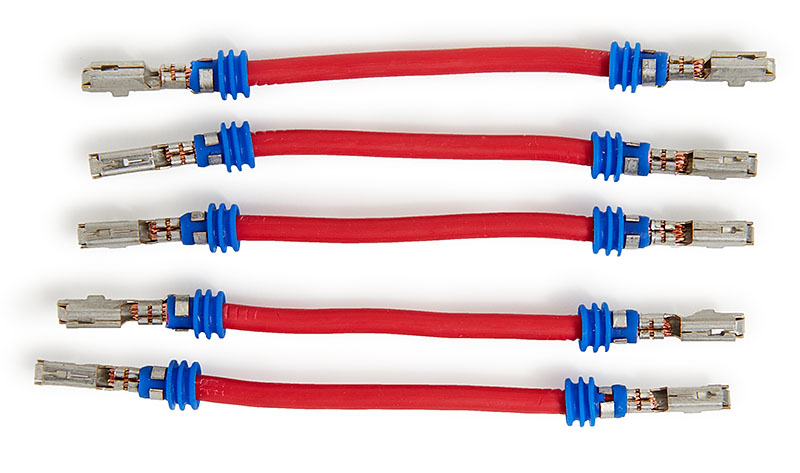
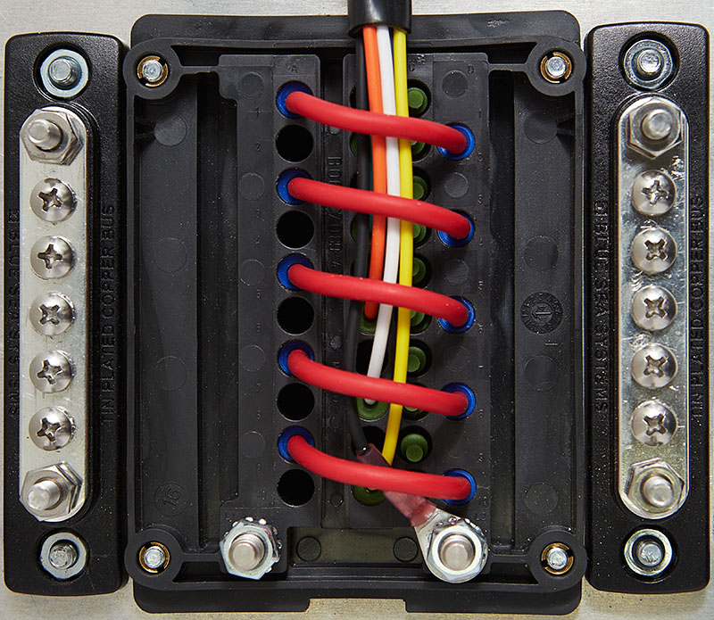
The next step is to insert the jumper wires. Start by bending the wire into a horseshoe shape, making sure that the terminals are facing the same direction.
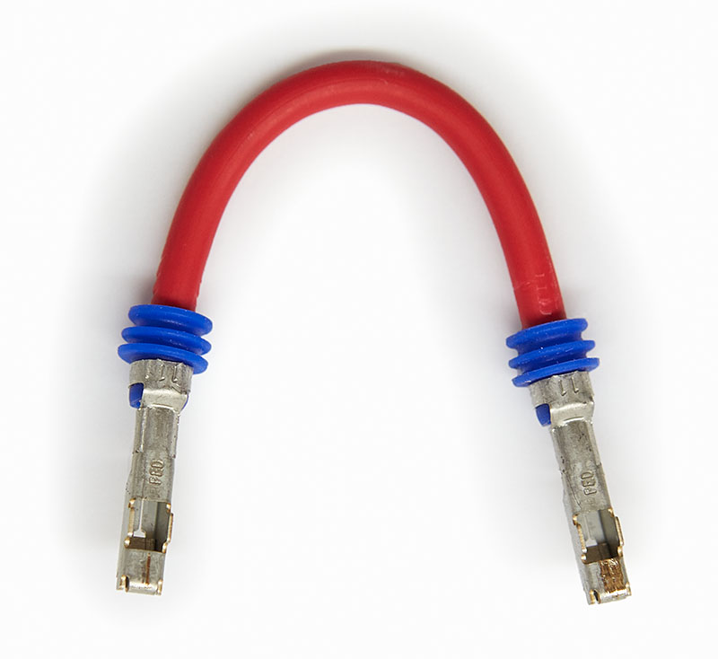
Then insert one end into an odd-numbered fuse cavity. Finally, insert the other end of each wire to pin 30 of it’s corresponding relay.
Continue with the remaining wires and it will look like the following when complete.
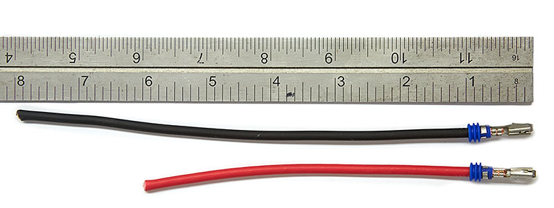
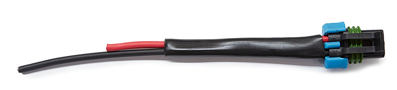
MAKING ACCESSORY CABLES
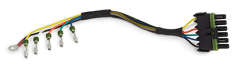
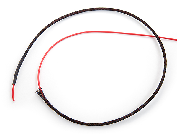
This section will outline the steps necessary to build the following cable assembly.
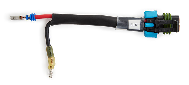
This cable and connector is what you use in the future to attach any accessories to your vehicle, such as lights and compressors. In total, you will need to make ten of these cable assemblies. Five will be for accessories through relays, and the other five will be for fused only, low-power, accessories.
The parts I’m specifically using in this step are the following:
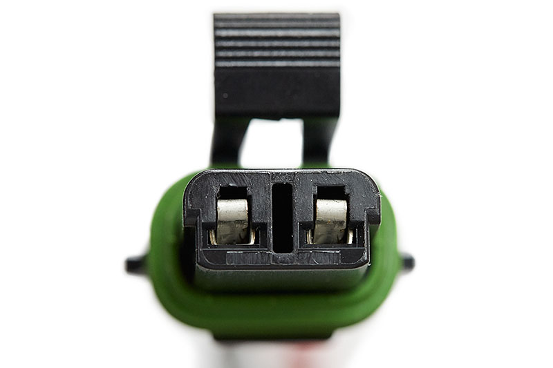
- Connector: Metri-Pack 280 Two-Way Female – 15300027
- Quantity: 10
- Terminal Position Assurance (TPA) clip: Metri-Pack 280 Terminal Position Assurance clip – 15300014
- Quantity: 10
- Terminals for connector: Metri-Pack 280 Sealed Tanged Female 12-10 AWG – 12077413
- Quantity: 20
- Terminals for RTMR: Metri-Pack 280 Sealed Tangless Female 12-10 AWG – 12110853
- Quantity: 10
- Cable seals: Metri-Pack 280, Blue 12 AWG – 12015193 / 15324981
- Quantity: 30
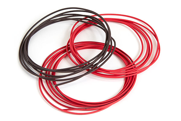
- Wire: 10 AWG TXL
- Colors: red, black
- Quantity: 55″ red, 75″ black
- Ring Terminals: 12-10 AWG heat shrink, #8 hole
- Quantity: 10
- Heat shrink: 1/2″ adhesive-lined black
- Quantity: 35″
- Heat shrink: 3/4″ clear
- Quantity: 10″
Please note that you will be using two different styles of Metri-Pack terminals. The Metri-Pack plugs use a “tanged” terminal, and the Bussmann RTMR uses “tangless” terminals.
Another detail to consider is that we are using two ground busbars, one on either side of the RTMR. I mention this because it makes a difference in how the cable assemblies are made. The five cables for the accessories through the relay are made slightly differently than the five cables for the fused-only accessories. The only difference is that they are mirror images of each other, which flips the terminal alignment. You’ll see what I’m talking about as we proceed.
This step is a bit more involved than anything we’ve done before. So let’s start by making a single cable assembly that can be used for a relay accessory. When complete, simply make four more identical cables. When done with these five, I’ll outline the differences for the remaining five cables.
Cut 10 AWG red wire to length, 5 1/2″.
Cut 10 AWG black wire longer than needed, approximately 7 1/2″.
Strip one end of each wire 7/32″ and slip on blue seals.
Using T-18 crimper, crimp Metri-Pack 280 Sealed Tanged Female 12-10 AWG terminals to each using setting “B”. Using T-18 crimper, crimp cable seal with setting “5”.
If you’re choosing to solder the terminals, do so now.
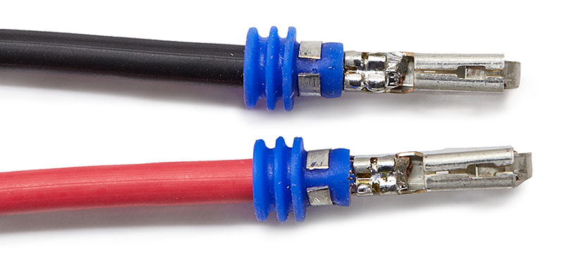
Insert into Metri-Pack plug with the red wire into the “A” hole and the black wire into the “B” hole. This isn’t a requirement, but you want to at least maintain consistency for all your cable assemblies. If you swap the order, all it does is orient the plug in the opposite direction.
Snap on blue Terminal Position Assurance clip. There is no specification as to which side the clip is attached to. I chose this orientation and maintained consistency for all cables.
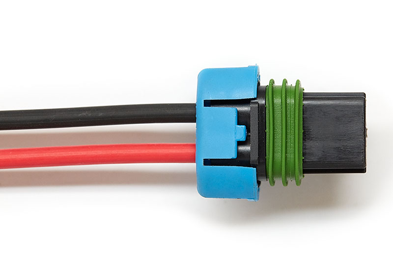
Cut 1/2″ diameter heat shrink tubing 3 1/2″ long.
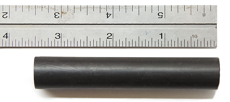
Slip on heat shrink all the way to the retainer clip and use a heat gun to shrink the tubing.
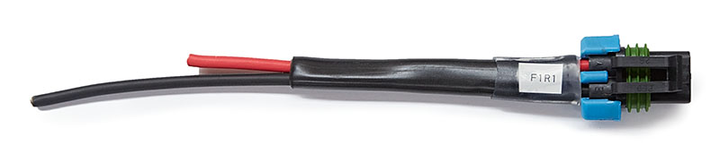
Print a label using a label maker to indicate which accessory this is. For this example, I’m inserting into the first relay, which is using the first fuse. Therefore, I labeled as “F1R1” to indicate Fuse #1 and Relay #1. I mentioned earlier that I’m using odd-numbered fuses, so the next cable would be labeled as “F3R2”. Last, use a 1″ long piece of 3/4″ clear heat shrink tubing to keep in place.
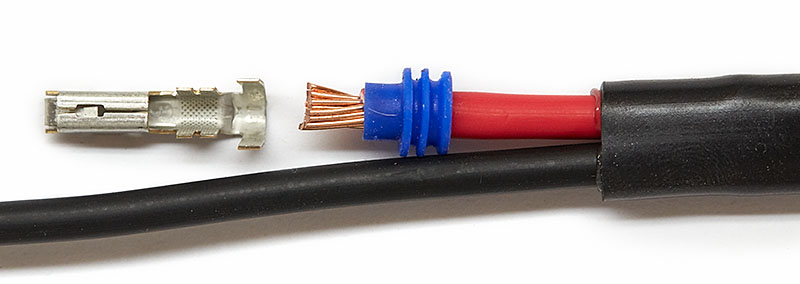
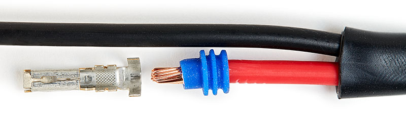
Slip on blue cable seal, strip the exposed end of red wire 7/32″, and slide seal into place:
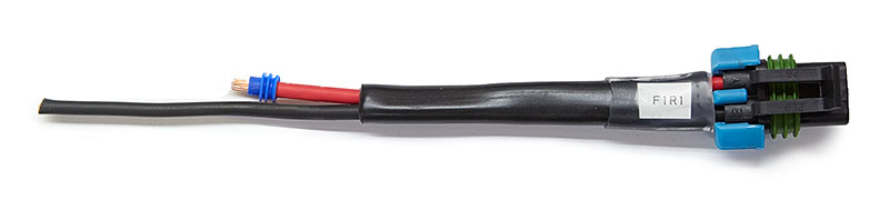
Align Metri-Pack 280 Sealed Tangless Female 12-10 AWG terminal as shown in the following image. Notice how with the cable laying flat on a table, the red wire is towards the top and the opening of the terminal crimps is towards you. This will ensure that the black wire is on the side near the Blue Sea busbar when the red wire is inserted into fuse block.
Crimp terminal with “B” setting, and crimp seal with “5” setting. If you choose to solder terminals, do so now.
Attach sealed 12-10 AWG heat-shrink ring terminal with #8 hole to correct position on busbar. For this example, the cable assembly will be inserted into the top relay, so I’m using the top busbar position. As each subsequent cable is inserted, I’ll use the next busbar position.
Bend the black wire to the side, push the switch harness wires towards the center, and temporarily slip the red wire into the fuse block to pin 87.
Do not seat all the way. We are simply putting the cable in place to align the black wire up against the ring terminal to determine what length to cut it at.
Align the black wire to the ring terminal, mark, and cut to length.
Remove cable assembly and ring terminal. Strip black wire 1/4″.

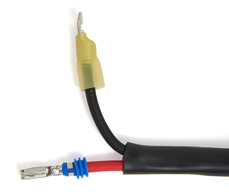
Lay the cable on a flat surface with the black wire bent out to the side as shown below. Slide on the ring terminal, and orient it so that the blade is angled 90° from the surface and facing towards the connector. This will ensure that the terminal it will lay flat once installed in the fuse block.
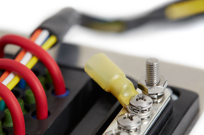
Crimp ring terminal, use heat gun to seal, and install permanently into fuse block. You’ll know the red wire is fully seated when it clicks into place.
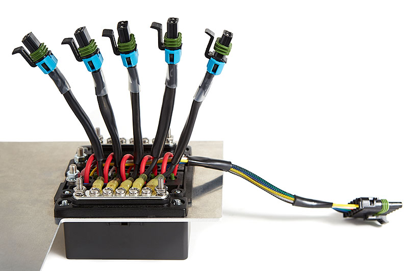
Once installed, it will look like this.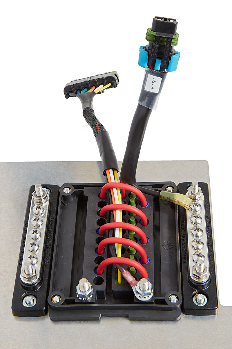
After that, make four more cables with the same technique, and it’ll look this this.
Now we need to make five more cables for the fused-only accessories. The overall process is exactly the same, but there is a subtle difference in the cable assembly process.
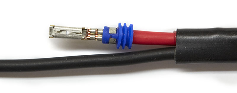
Simply put, we need to position the terminal differently on the red wire that inserts into the RTMR. All you need to do is flip it 180°, as the following image illustrates. This is opposite of how you did it before. Whereas the red wire was on top with the cable laying flat on a table, the red wire is now on the bottom, and you position the terminal crimps facing towards you as before. When the red wire is inserted into the RTMR, the black ground wire will stick out to the other side towards the second busbar.
As an additional observation, when you slip on the ring terminal to the black wire for the ground busbar, it will look like the following. It’s still facing up towards the Metri-Pack connector, but the image shows that the terminal is facing the opposite direction.
These five cables are not using any relays. Instead, they are inserted into the even-numberd fuse positions. So the first cable will be in fuse #2, the second in fuse #4, an so forth. After making and installing the five fused-only accessory cables, it will look like the following image.
Completing The Build
The final step is making and connecting the power and ground cables as well as inserting relays.
Parts used in this section:
- Fuse holer: Blue Sea ANL Fuse Holder with Insulating Cover 30- 300A, Part #5005
- Quantity: 1
- Fuse: 80A ANL
- Quantity: 1
- Wire: 4 AWG welding wire
- Colors: red, black
- Quantity: About 2-4′ each color.
- Copper Crimp Lug: 4 AWG with 1/4″ hole
- Quantity: 2 (possibly more with your setup)
- Copper Crimp Lug: 4 AWG with 5/16″ hole
- Quantity: 2 (possibly more with your setup)
- Copper Crimp Lug: 4 AWG with 3/8″ hole
- Quantity: 0 (possibly more with your setup)
- Copper Crimp Lug: 4 AWG with 1/2″ hole
- Quantity: 0 (possibly more with your setup)
- Wire loom: 1/2″ expandable braided sleeving
- Quantity: About 2-6′
- Wire: 10 AWG TXL
- Colors: black
- Quantity: 3″
- Ring terminals: 12-10 AWG heat shrink with 1/4″ hole
- Quantity: 1
- Ring terminals: 12-10 AWG heat shrink with 5/16″ hole
- Quantity: 1
- Heat shrink: 3/4″ adhesive lined
- Colors: red, black
- Quantity: about 6″ of each color
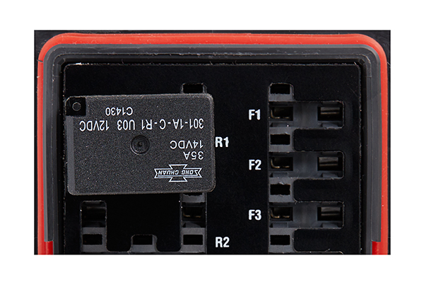
- Relays: Song Chuan 301-1A-C-R1 four-pin
- Quantity: 5
Let’s begin by installing the relays. As mentioned previously, we are installing these upside down. So start with one relay as shown below, and then continue until all five are inserted.
I won’t be installing the individual fuses now. I do that whenever I install an accessory to the vehicle. This is because I don’t know what sized fuse I’m going to need until the accessory and wire size are chosen.
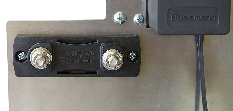
Next, we need an overall circuit protection device for the RTMR. I used an ANL fuse holder, but you could use a circuit breaker if you prefer. This was installed on the top-side of the bracket.
Now let’s make a supply wire to provide power from the ANL fuse holder to the RTMR.

I made mine just long enough to connect the two together without any slack. And as before, I used 1/2″ braided sleeving and 3/4″ adhesive-lined heat shrink tubing. The crimp lugs used were 4 AWG with 5/16″ hole. I found that it’s easiest to cut the cable in place as follows:
- cut wire longer than needed
- strip one end
- crimp lug
- install to fuse holder
- maneuver cable into position
- mark length
- cut
- strip insulation
- temporarily slip on second lug
- mark position with sharpie across lug and insulation
- remove cable
- crimp second lug while aligning sharpie marks
- install braided sleeving and tubing
- permanently install cable
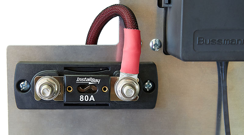
When complete, one end attaches to the ANL fuse holder.
The other end attaches to the second internal bus providing power to all of the fuses.
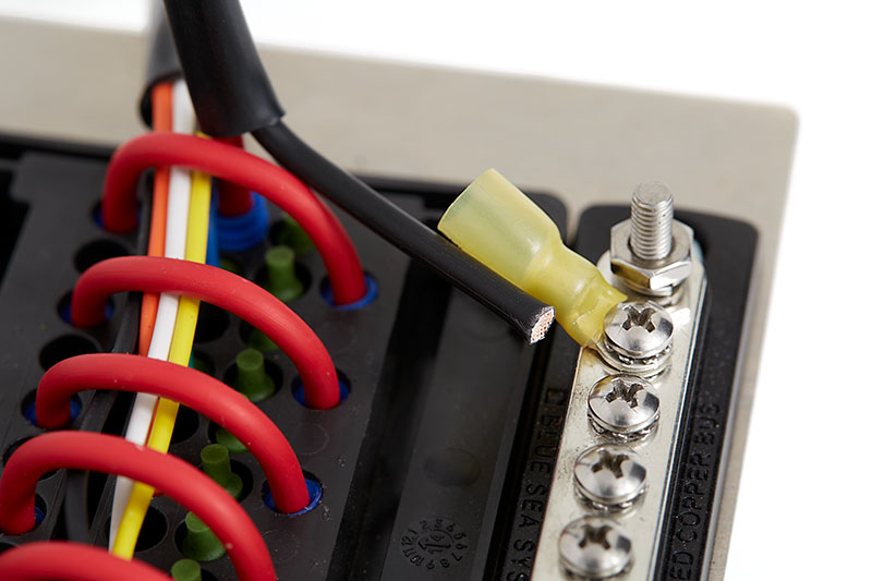
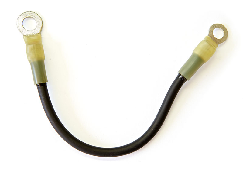
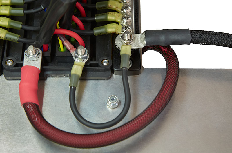
Next, we need to make a short cable to connect the second internal ground busbar to the external ground busbars. If you remember, this second internal busbar is not handling a lot of current. This is the ground point for pin 85 of all five relays. The maximum current with all five relays engaged will be less than 1 amp. Therefore, a jumper wire of 18 AWG from the internal busbar to the external busbar will be sufficient. But with that said, I chose to use 10 AWG wire strictly for the durability.
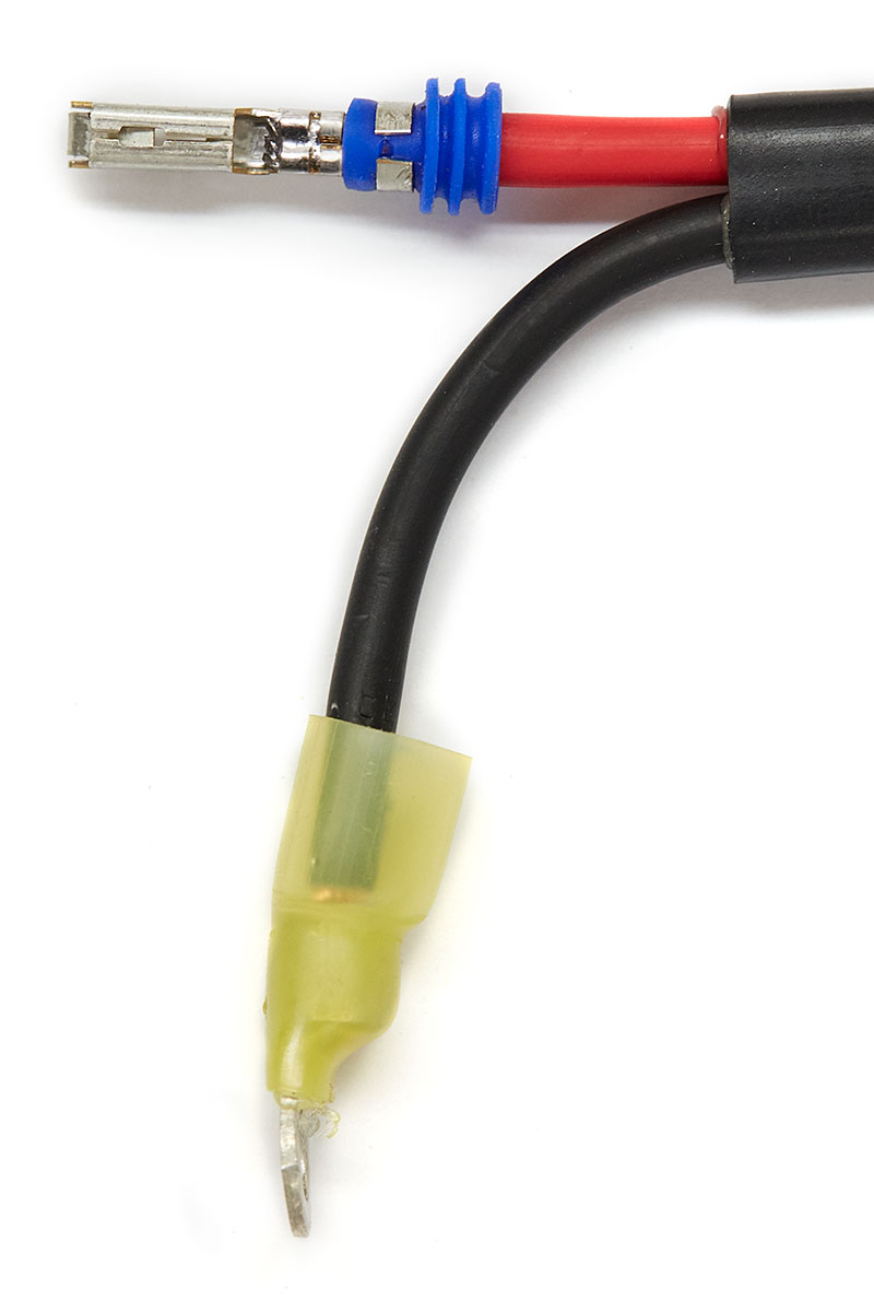
Cut a 3″ length of 10 AWG black wire. On one end, crimp on a heat shrink ring terminal with a 1/4″ hole. On the other, crimp on a heat shrink ring terminal with a 5/16″ hole. Use a heat gun to shrink.
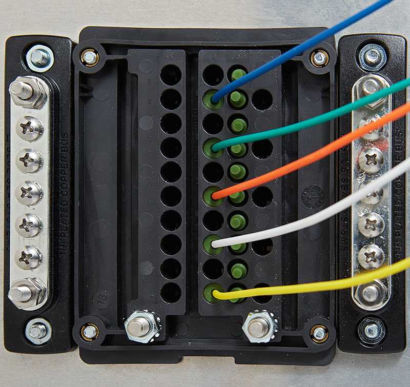
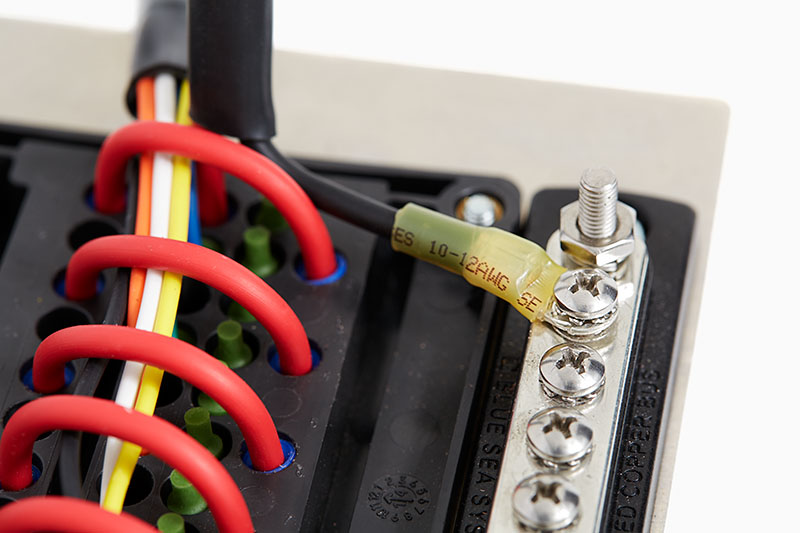
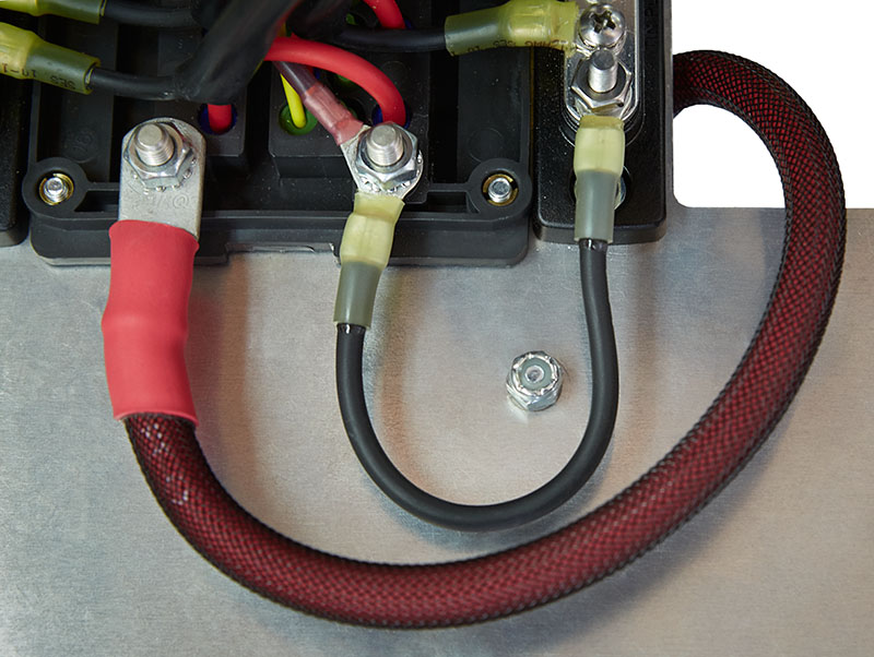
Secure in place from the 2nd internal busbar to the external busbar immediately adjacent.
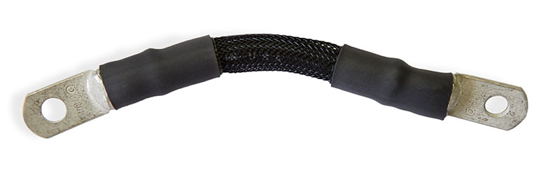
We need to connect the external ground busbars together. Cut a piece of 4 AWG welding wire about 4″ long, strip the ends, and crimp on a 4 AWG lug with a 1/4″ hole to each end. Use 1/2″ braided sleeving and 3/4″ heat shrink to seal.
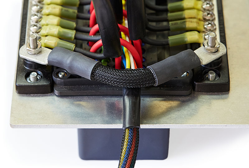
Secure the two busbars together at the ends where the switch harness exits the enclosure.
At this point, the Bussmann RTMR is officially complete. However, for installation, we need to make two more cables:
- positive cable to connect the battery to the input side of the ANL fuse
- ground cable to connect the external busbar to the battery negative post
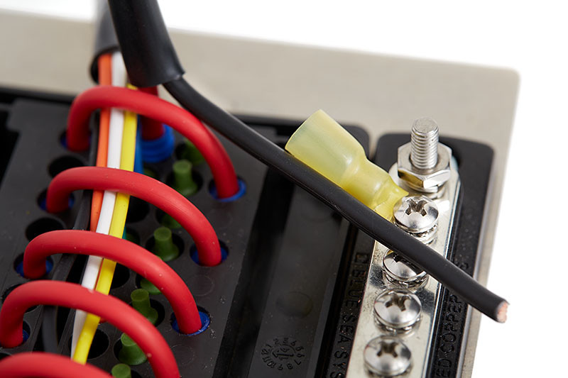
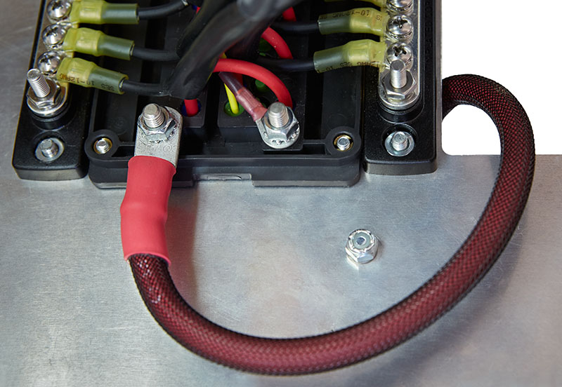
These will be cut to a custom length based off of your needs. The following picture shows where one end of the ground cable is connected to the external busbar.
The positive cable will connect from your battery to the input side of the ANL fuse holder or circuit breaker. I’m not detailing the specifics of these cables, because the length is dependent on your installation. But at this point, you should know the necessary steps to complete.
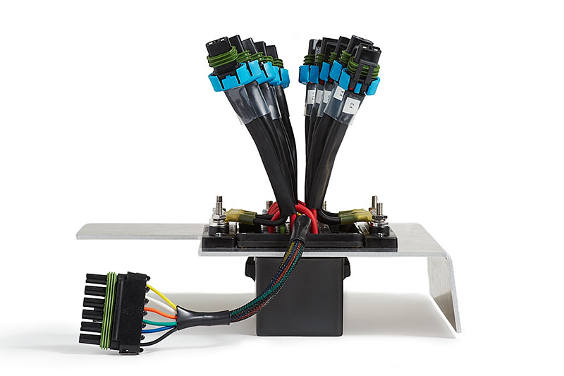
CONCLUSION
In this part, I have shown you how to build a Bussmann RTMR. I’ve detailed out to make the necessary parts and how to connect them. The final step is to install the enclosure in your vehicle, which I’ll outline in the next part, Part 6 – Installation.