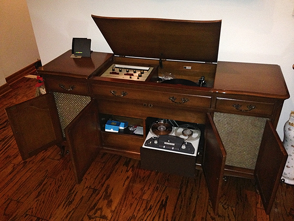
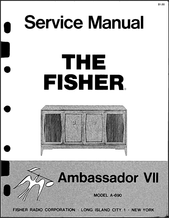
My father-in-law is the original owner of this 1965 Fisher Ambassador VII stereo console. Unfortunately, it stopped working many years ago, long before I met my wife, and it has sat idle ever since. A few months ago, he asked me if I could get it working before Christmas. Not one to turn away from a challenge, I embraced this project and was successful.
In this article, I’ll walk you through the steps I performed to get the stereo working. Keep in mind, however, that I’m not an expert with this sort of thing, so it’s very possible that I either approached solving the problem incorrectly or even made mistakes along the way. I have a basic understanding of electronics, but what I lack in knowledge, I make up for in perseverance. Additionally, I have two co-workers who are very skilled in this area, and they loaned me some test equipment and served as mentors throughout the project.
Before proceeding, I give you this word of warning. I take no responsibility for damage, accidents, or injuries resulting from the use of any information provided in the article. Any electrical work or modifications to your stereo or personal property is done so at your own risk.
As stated earlier, this was my father-in-law’s stereo that he asked me to restore. He was the original owner, and the unit was in really good condition. However, it wasn’t working, and I was unaware of how long it had been this way, perhaps ten years or more. His console included a L-22 reel-to-reel tape recorder and a Dual 1228 turntable, which replaced the original Dual 1009.
The first investigative step was to discover the symptoms and formulate a game plan. Immediately, I discovered that the main 3.2A slo-blo fuse was blown, so I knew we had a significant problem on hand. Although my experience with electronic repair and old radio restoration is limited to none, I was aware that old capacitors dry out and effectively act as high value resistors, thus allowing DC current to pass through. In turn, this causes additional problems. Therefore, I needed to approach this systematically and not rush into anything, so I chose to remove the amplifier and tuner and take them home to work on. This was going to be a big project.
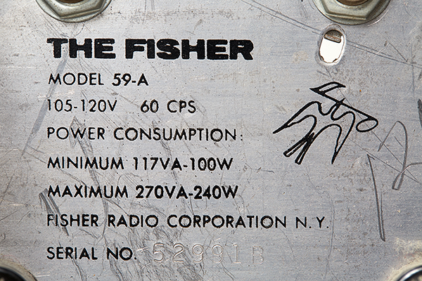
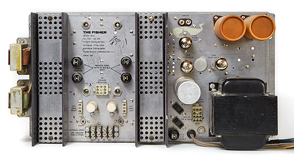
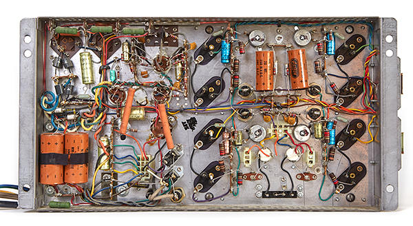
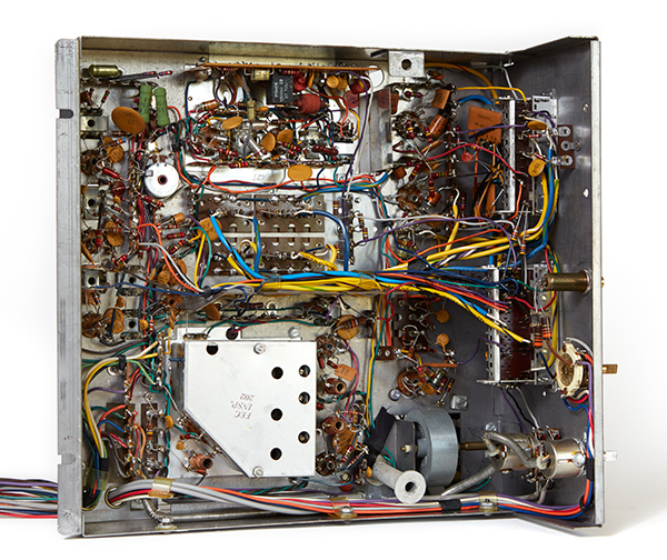
The amplifier was a 59-A:
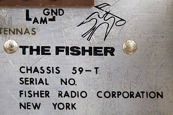
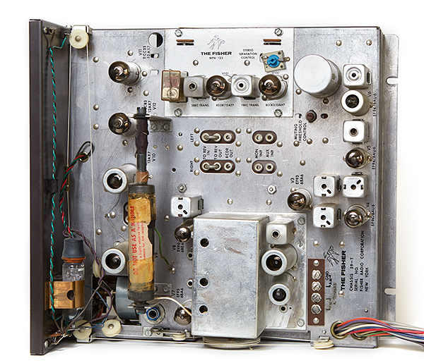
The tuner was a 59-T:
My father-in-law is a meticulous man and kept detailed records. Included with the stereo console, I found an envelope with receipts that I was able to assemble a rough historical timeline of the stereo.
1965:
Purchased new by my father-in-law.
10-25-1976:
- Audio Hospital in Canoga Park, CA replaced both 6HU8 tubes and one 12AX7 in the 59-A amplifier.
- Audio Hospital replaced output transistors for the left channel, Q1, Q2, Q3, & Q4, with ECG121 transistors in the 59-A amplifer
12-2-1977:
- Audio Hospital did a complete dis-assembly, cleaning, lubrication, and reassembly of the 59-A amplifier. I’m not exactly sure what this means.
Sometime a few years ago:
- My brother-in-law replaced many tubes. There are no notes indicating which ones or why.
TROUBLESHOOTING
With the amplifier and tuner at my house, my general game plan was to test the tubes; replace all of the electrolytic and mylar capacitors; insert new fuses; test and replace any transistors; clean connectors, switch contacts and potentiometers; and calibrate the amplifier.
I was able to find an official service manual from the Fisher Consoles website for a 1965 Fisher Ambassador VII. This was vital in helping me restore the console. Not only did it provide a schematic of the amplifier and tuner, but a detailed parts list and instructions on how to calibrate the amplifier and tuner.
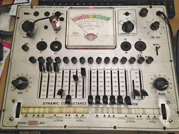
I borrowed an Eico 667 tube tester from a co-worker and discovered that all of the tubes were good with the exception of a single 12AT7 that was used in the multiplex decoder of the tuner. I therefore purchased a new old stock RFT ECC81 / 12AT7 from The Tube Store, which I chose for it’s low noise and low microphonics.
PARTS
The next order of business was to replace all of the electrolytic and mylar capacitors. This was going to be a lot of work, but I first had to find replacement components. I inquired with Jim McShane and Metalbone for restoration kits, but neither were able to help me. Therefore, I had to source new components individually, which was quite a bit of work. I didn’t want to sacrifice by using cheap components, so I chose Nichicon UPW capacitors for replacement filter caps and Nichicon UKL capacitors for all remaining electrolytics. The only exception was for the multi-section capacitors. On both the amplifier and tuner, there were four-section capacitors where I used Nichicon UCS capacitors due to their size. Their smaller size allowed me to stuff the cans with new capacitors so that I could keep the original appearance of the stereo. I’ll discuss this more later. Anyway, all of these capacitors had radial leads and not axial, as the originals were, so I had to get a little creative during installation with wiring and heat shrink.
Additionally, all film capacitors were replaced with Cornell Dubilier polypropylene with two exceptions. The first exception was for the mains 0.01µF filter cap, C27. This was replaced with a Kemet XY-rated safety capacitor. These XY-rated capacitors are used so that if they fail, they do not fail short and make the chassis potential hot with 120V. To learn more about XY-rated capacitors, see this page at Just Radios. The second exception was a Vishay 0.01µF cap used for C26.
Here are two Excel spreadsheets detailing all of the replacement capacitors I used, along with direct links to Mouser Electronics where I purchased them.
1965_Fisher_Ambassador_59-A_Capacitors
1965_Fisher_Ambassador_59-T_Capacitors
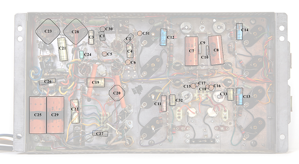
While I was waiting for parts to arrive, I took the time to outline the location all of capacitors in the amplifier. This was time well spent, because it really helped speed up the process when I got down to replacing parts. Additionally, I was able to become more familiar with the amplifier, it’s design, and some errors with the schematic.
59-A amplifier capacitor locations:
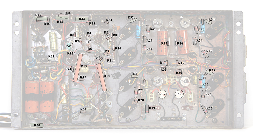
Although I didn’t have any plans on replacing the resistors, I also noted where they were physically located. As I replaced capacitors, I checked resistor values along the way. None were out of spec, so none were replaced.
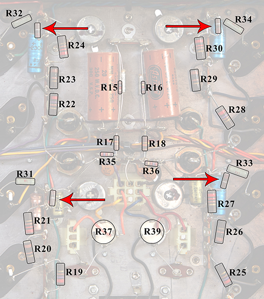
59-A amplifier resistor locations:
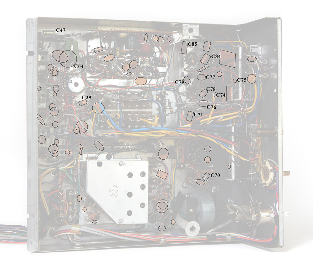
The tuner on the other hand had many more components and didn’t need the level of detail needed for all parts locations. Therefore, I simply noted the location of specific electrolytic and mylar capacitors that I planned on replacing.
59-T amplifier capacitor locations:
I also tested the transistors using a Fluke multimeter. Out of the eight transistors, four had been previously replaced with ECG121 transistors. These four were still good, yet the other four original transistors were bad.
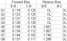
To understand the test results, you can think of a transistor as two diodes. When using the Fluke multimeter in diode test mode, the result indicates the voltage drop across the component under test. The table above shows acceptable results for the Forward Bias voltage drop of each transistor, both the Emitter/Base and the Collector/Base. The Reverse Bias, however, should be OL (open loop), which indicates an open circuit and is the desired reading. As you can see, there is a voltage drop across the Base/Emitter junction for transistors Q5-Q8. Therefore, these four transistors needed replacement
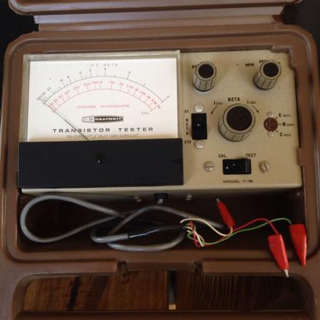
New replacement germanium transistors are no longer available, so I searched eBay and eventually won two auctions for two ECG121 transistors each. Luckily, one shipment came with four transistors instead of two, so I had a total of six new old stock transistors. This ended up working out to my advantage when trying to find matched pairs. After measuring the gain of all transistors with a Heathkit IT-18, I was able to find more closely matched pairs. This included mixing up the new and pre-existing ECG121 transistors for the best combinations.
Besides the capacitors and transistors, there are only a couple other parts that may have needed replacement. There were only a few diodes in the circuit, and I didn’t expect any to be bad. Yet if any needed replacing, 1n4007’s would be suitable. Also, I purchased Bourns 1/2W 10Ω potentiometers with the expectation that the biasing pots for the output power stage would need replacing. From what I had learned, these old pots were notorious for failing.
SCHEMATIC ERRORS
Waiting for parts gave me time to really learn the design by studying the schematic and electrical connections. Along the way, I discovered several errors with the 59-T tuner schematic and parts list. The first error was regarding the AUTO SHUTOFF switch. It was originally drawn as follows:
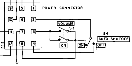
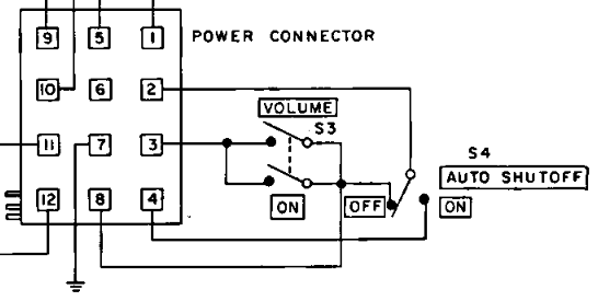
The problem was that the labeling for the AUTO SHUTOFF switch was incorrect; the ON and OFF labels were backwards. It should be drawn as follows:
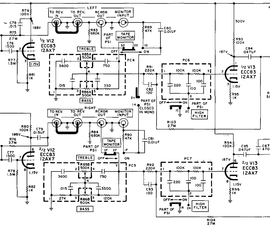
Another error on the tuner schematic was with the terminal labels for tubes V12 and V13, which are both split in half on the schematic. Each half of the triode indicated connections to the same terminals. The incorrect schematic was as follows:

The schematic with correct terminal labels should be as follows:
I discovered a few errors with the 59-A power supply. In the Parts Description List for the power supply, the values for C1 and C2 are listed as 022µF. A decimal point is missing and should be listed as 0.022µF. They are, however, correctly indicated on the schematic.
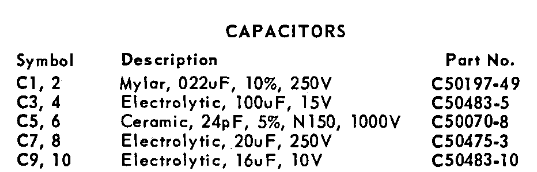
The correct values should be as follows:

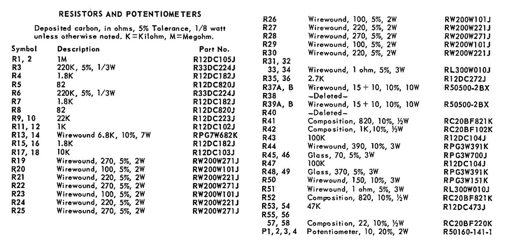
During the process of diagramming the resistor locations on the 59-A, I noticed a rather significant error in the schematic. According to the resistor parts list, there were four 22Ω resistors labeled as R55, R56, R57, R58 that I couldn’t find on the schematic. So after some diligent searching of the amplifier, I discovered four resistors that parallel P1, P2, P3, & P4.
Here’s the parts list:
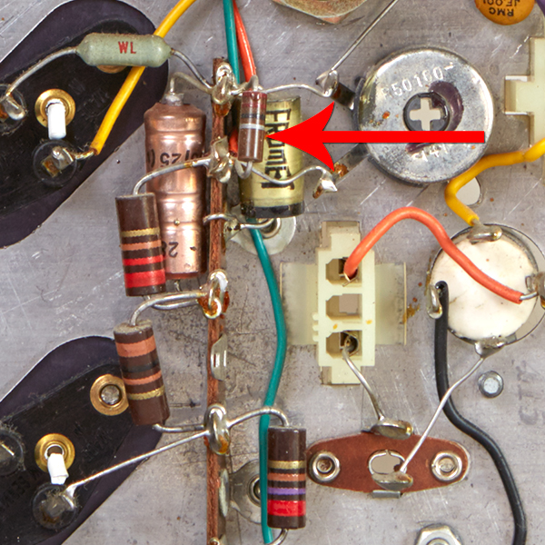
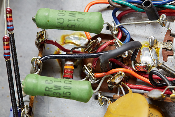
Here’s the four resistors in question:
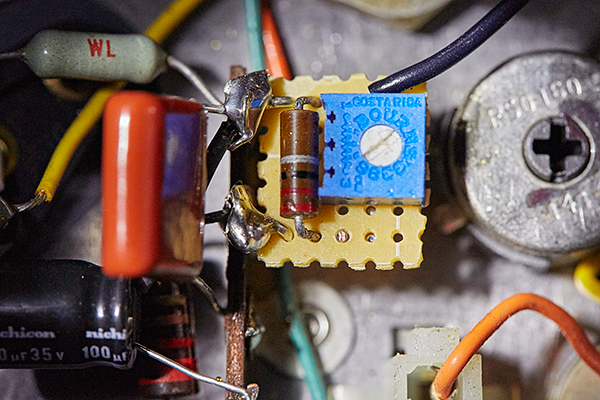
And here’s a closeup of what is presumably labeled as R55, which parallels P1
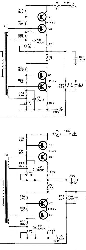
Here’s the schematic as originally drawn with the missing resistors:
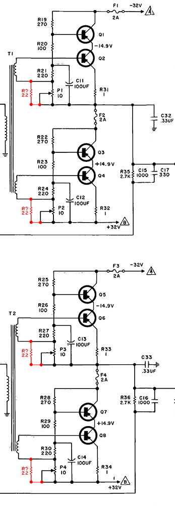
Here’s a revised schematic with the resistors in question marked in red. I have them labeled here as question marks, but based off of Fisher’s typical labeling scheme, they’re most likely R55, R56, R57, & R58 from top to bottom.
PARTS REPLACEMENT
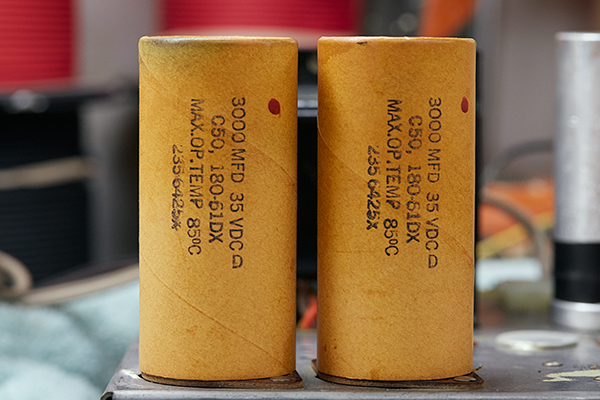
Once the replacement parts arrived, I began working on the 59-A power supply and amplifier. The first parts to replace would be the most difficult, which were the main filter capacitors, both the 3000µF caps as well as the capacitors in the four section can.
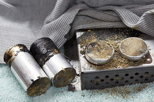
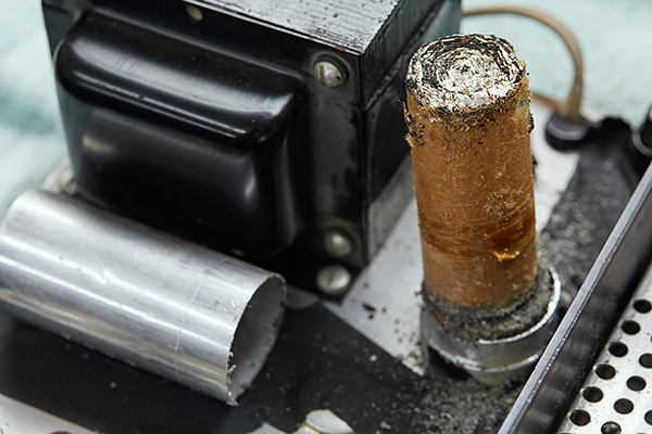
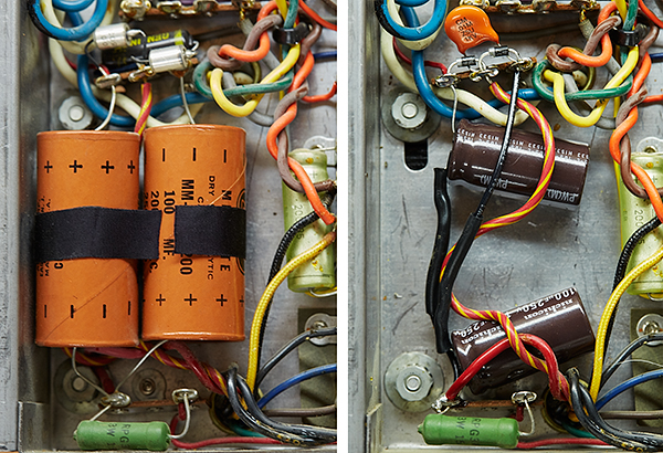
Using a heat-gun, I heated the cardboard tubes on the main 3000µF caps to soften the glue. This allowed me to easily pull off the tubes. I then used a hack-saw blade wrapped in a rag and slowly cut off the cans. As the picture shows, the capacitors were dried up and hard as a rock.
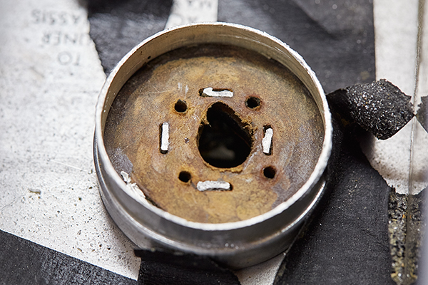
The old cans were disposed of and the bases were cleaned up with a Dremel tool. New capacitors were inserted, soldered, and hot-glued in place.
The original cardboard tubes were slipped back over the base and held in place with friction alone.
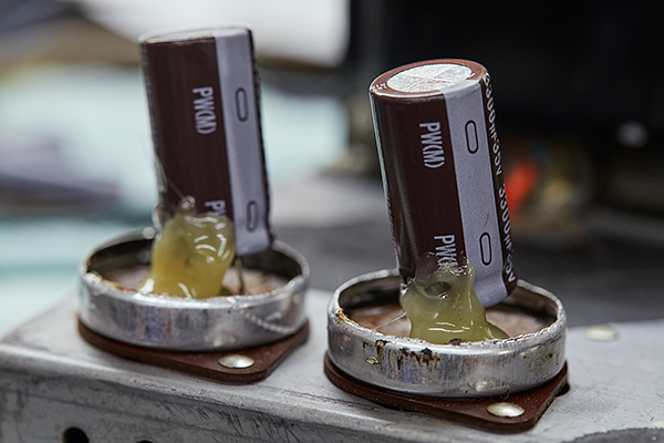
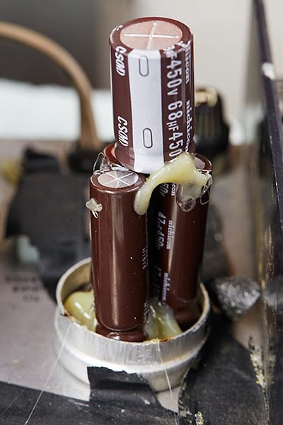
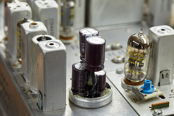
The multi-section can was a similar process, although it didn’t have a cardboard tube. Since it was the can alone, I could not dispose of it and approached restoration a bit differently. After cutting off the metal can, the guts of the capacitors were still in place. This was not as dried out as the previous capacitors.
I used a Dremel tool as before to clean up the base. Afterwards, I drilled holes for the new capacitor leads. Each capacitor had it’s own small hole for the positive lead while all the grounds leads were tied together and oriented through a larger hole in the center.
With a little creativity and heat shrink, I was able to position all four new capacitors securely and safely so that none of the positive leads touched each other or the chassis.
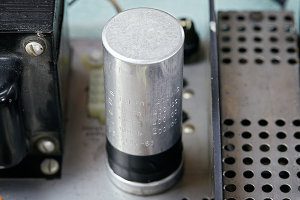
To secure the metal can back in place to retain the original look, I used tape. The following picture shows black electrical tape, but I ended up using silver metal foil tape, which blends in better.
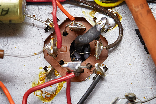
On the underside, you can see how the positive leads connect to the original posts, and the grounds, all soldered together and protected with heat shrink, are terminated on the chassis.
With the most difficult capacitor replacement completed, I continued replacing all of the remaining electrolytic and mylar capacitors. Here’s an example where I’ve replaced electrolytic capacitors C25 and C29, a mylar capacitor C26, as well as two diodes CR1 and CR2. Notice that the replacement electrolytic caps are now radial instead of axial and that I needed to extend the leads with wire and protect them with heat shrink. This was typical of many other replacements.
After all of the capacitors were replaced, I tested the biasing potentiometers and unsurprisingly discovered that there was inconsistent readings from open to short to all over the place as I adjusted them. Therefore, these were replaced with small 1/2W Bourns 10Ω pots. Although the original pots were rated at 2W, the Bourns 1/2W are more than sufficient to handle the current needed to bias the transistors. The following picture shows how I mounted them with the original 22Ω resistor in parallel with the pot. I left the old potentiometers in place, although I disconnected their terminals and were left out of circuit.
With the parts replacement completed on the power amplifier, it was time to move on to the tuner. This was going to be a much quicker job due to the fewer number of parts. Similar to the power supply, the tuner had a multi-section capacitor that needed new parts.
The underside had many more components and wires to deal with, but I was successful in the end.
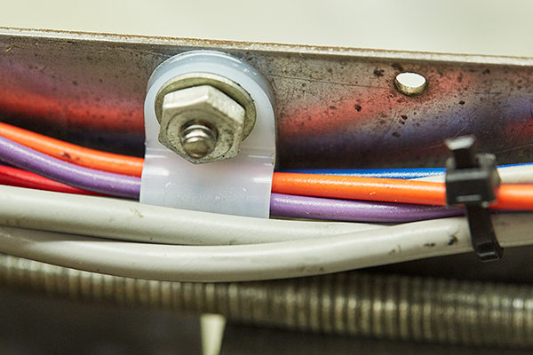
Another small detail that needed attention was the wiring tie-downs. The plastic had deteriorated to such a degree that they were breaking apart. So, I replaced them all.
POWERING UP
When it came time to apply power for the first time, I was very patient. I first tested for any shorts in all transformer windings. Once everything checked out, I started with the transistors and tubes out of circuit and used a variac to ramp up power slowly, pausing periodically while checking voltages. Once AC and DC voltages were verified, I powered down, installed the tubes and checked again. With the tubes in place, the high DC voltages fell more in line.
Finally, it was time to install the transistors and calibrate the output stage. To bias the transistors, I followed the service manual as closely as possible, which was very straight-forward, but I lacked a few tools specified:
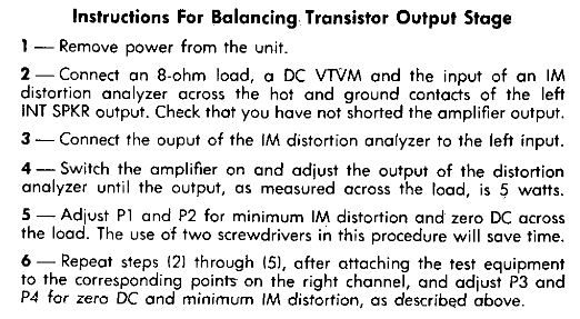
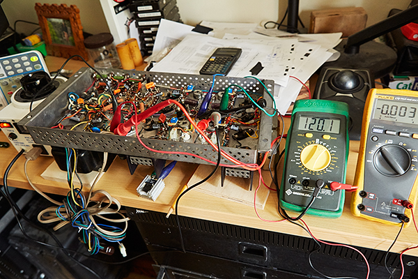
I did not own a vacuum tube volt meter nor an IM distortion analyzer, but I did own a multimeter and a digital oscilloscope with FFT functionality. Additionally, I borrowed a signal generator from a co-worker. So my technique to bias the output transistors was as follows:
- Using a signal generator, I input a 1kHz tone on one channel while adjusting its level so that I measured 6.44V across an 8.3Ω non-inductive load resistor on the respective output. This gave me 5W of power at the output. The input signal ended up being 675mV on the left channel and 660mV on the right.
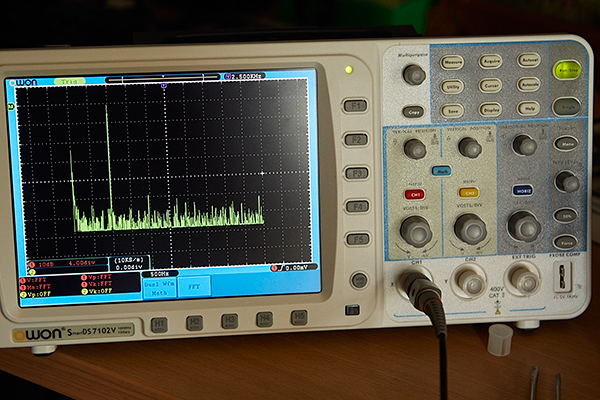
- I connected an oscilloscope in FFT mode across the dummy load as well as a DC volt meter.
- With the biasing pots beginning at the lowest resistance, I adjusted both pots simultaneously to achieve 0V DC across the dummy load while trying to minimize the harmonic distortion. With the oscilloscope in FFT mode, I could clearly see all the harmonics affected with adjustment, most specifically the third harmonic, which is associated with crossover distortion. For more information about crossover distortion, read this article at Aiken Amps.
- When the left channel was calibrated, I moved on to the right.
After the amplifier was calibrated, it was time to connect the tuner and see if I had sound. This was the big moment! With the equipment at my house and the console at my father-in-laws, I couldn’t use the original speakers. Therefore, I used a pair of my own speakers, B&W 704’s. This was probably a better choice anyways, because these were speakers that I knew worked and sounded good. This would take out the additional variable of the original speakers being bad. Anyway, with the components sitting on a cardboard box and a towel, I connected the them together, attached an antenna, and turned it on. Whala! I had audio, and it actually sounded really good. With only a few adjustments of the bass and treble controls, I had a rather pleasing sound, which the following video shows. This is straight off my iPhone.
https://youtu.be/OddCyhSngN4
I had decent AM and FM reception and the dial was aligned close enough for me. This was great news, because I didn’t want to get into aligning the IF, RF, and the dial; that’s a little bit out of my skill-set. I was also happy that the Station Indicator and Stereo Beacon lamp worked as they should. Next, I tested the AUX inputs with another source, and that worked as well. So all in all, it was a success. The only remaining steps were to re-install the components back in the cabinet and test the phonograph and reel-to-reel.
FINAL INSTALLATION
This past weekend, I re-installed the tuner and ampilfier. After all of the connections were made, I powered up and listened to the sound quality on the original speakers. Yup! As I suspected, they didn’t sound so good. There was a bit of a buzz and distortion on the higher frequencies, so I’m going to have to look into restoring the speakers. I may have to replace the filter caps and re-cone the speakers, but this will have to wait until after Christmas.
The phonograph worked and played records, yet the automatic gimbal arm didn’t function as it should. So that’s another item that needs addressing.
The reel-to-reel worked and we were able to listen to some recordings from 1967 of my wife, her sisters and mother singing along with some old songs. Wow! You should have seen the look on my father-in-laws face. His smile was from ear to ear, and I could see him falling back in time. All my hard work and time spent restoring the stereo was well worth it. Merry Christmas to my father-in-law!