This is part 4 in a series of tutorials teaching you how to build a Bussmann RTMR fuse/relay block. In previous parts, we’ve discussed what the Bussmann RTMR is and why you would want one. I’ve also outlined all of the necessary parts, tools, and techniques needed to complete this project. In this part, I’m going to talk in more detail about the RTMR, relays, wiring, and schematics.
Let me begin by saying that this tutorial is not written to teach you the basics of electricity. There are far better tutorials and sources of information for you to learn from. Furthermore, entire books have been written about the subject, so I wouldn’t even be able to do it justice.
Instead, I’m going to talk very specifically about what you need to know in order to wire the Bussmann RTMR enclosure and accessories.
- How a Relay Works
- Bussman RTMR Details
- Connections
- Accessory Grounds
- Wire Gauge
- Connectors
And as a reminder, I take no responsibility for damage, accidents, or injuries resulting from the fabrication or installation of any electrical modifications to your vehicle. You do so at your own risk.
How a Relay Works
The Bussmann RTMR uses ISO 280 Micro or Mini relays, with 2.8 mm terminals, and can accommodate either 4-pin or 5-pin relays. But what’s the difference? And what exactly is a relay and why do you want to use one?
A relay is an electrical component that is basically a switch. Many relays use an electromagnet to engage the switch, and are used where you would want a low powered circuit to control a high powered circuit. This is done for safety reasons.
For example, in our application, we will have a switch in the vehicle cabin. To be safe, we want this to be low current. When actuated, a low-powered signal energizes the electromagnet in the relay which triggers the internal switch and allows high current to flow to the accessory. So the switch at your fingertips is the low-powered circuit used to control the high-powered circuit of your accessory via the relay.
Automotive relays typically come in either 4-pin or 5-pin versions. These pins, or terminals, have standard designations:
- 30 = constant power from battery positive terminal (direct)
- 85 = coil ground
- 86 = coil power
- 87 = switched power to accessory
- 87a = normally closed contact with power connected from pin 30 (on 5-pin relays)
The Bussmann RTMR can use either version, but I find that 4-pin relays are sufficient for my needs. I simply want a switch in my vehicle to turn an accessory on or off. Therefore, this tutorial focuses on 4-pin relays only.
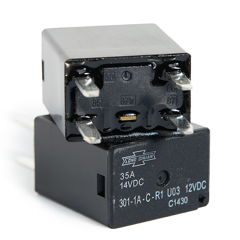
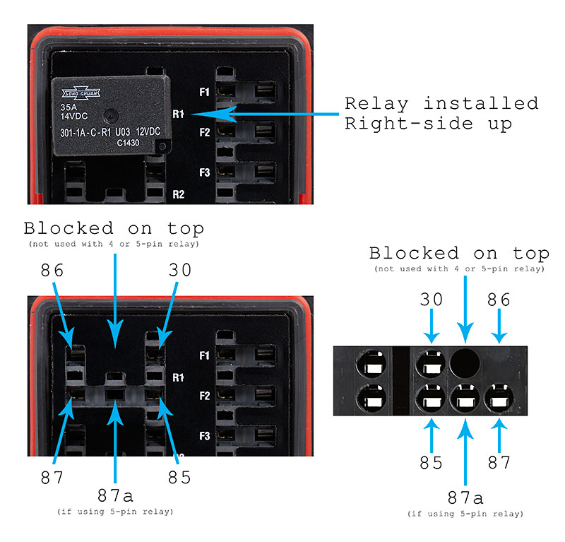
The relays we’ll be using are Song Chuan 301-1A-C-R1, which can be purchased from Waytek Wire or Mouser. Notice in the following picture how the pins are labeled on the bottom of the relay. You can even see where the fifth pin, 87a, would be if this was a 5-pin relay. Because the pins are in specific positions, it makes a difference how the relay is inserted into the Bussmann RTMR. I’ll talk in more detail about this later.
For now, let me show you a simple wiring diagram that details how to connect a switch and accessory to a relay.
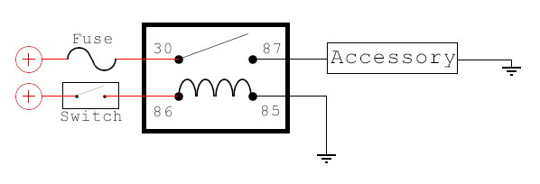
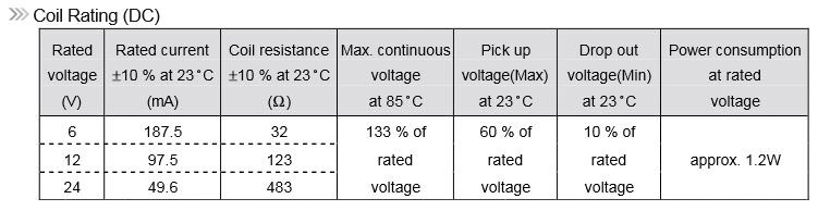
From this diagram, you can see that we have a physical switch, which will be inside our vehicle cabin. This supplies a positive signal to pin 86 of the relay. This pin is the input terminal to the coil inside the relay. This configuration is called “switched-power”, because the switch is turning power on and off to the relay. This is a low-current circuit, which is 97.5mA at 12 volts per the datasheet for the relays I’m using.
Contrast this with a typical accessory such as a 100 watt off-road light that uses over 8 amps at 12 volts. That’s 80 times more current and something you don’t want running through a switch at your fingertips.
When current is sent to the coil, it creates a magnetic field that closes the internal switch. With power connected to pin 30 directly from the battery and with the accessory connected to pin 87, the circuit is complete when the switch is closed. High power flows to the accessory directly through the relay and not your switch.
Now that you understand the basics of connecting an accessory to a relay, keep this in mind as I outline the details of the Bussmann RTMR.
Bussmann RTMR Details
As stated in Part 2 – Parts, there are several different configurations of the Bussmann RTMR. For this tutorial, I’m specifically using model 15303-2-2-4, which accommodates five relays and ten fuses. It also has two internal busbars. Let’s look at the details of this particular configuration and how we would wire it. Once you understand this, you could easily adapt what you’ve learned to any of the other RTMR enclosures.
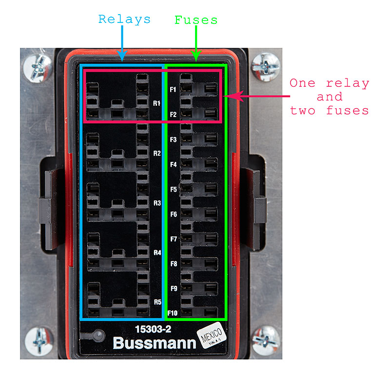
When first looking at the Bussmann RTMR, you might be quickly overwhelmed with the number of holes, or cavities as they’re called. It’s very similar to looking at a mixing console in a recording studio. There’s a whole lot of the same going on, and it can be dizzying at first sight. On a mixing console, you just need to learn one channel strip and you understand the majority of the mixing board. Similarly, all you need to learn on the RTMR is two rows of cavities, and the remaining simply repeat. So let’s break it down.
On the top of the RTMR, you’ll see that the relays are down the left side. For each relay, there are five insertion cavities to accept the male terminals. Down the right side are two insertion cavities for each fuse. You’ll quickly see that a relay takes up two rows of cavities, yet a fuse only takes one. Therefore, for each relay position, there are two fuses. But the physical layout does not imply that the relay and fuses are connected together.
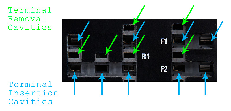
If you look at the cavities in more detail, you’ll notice two different types. One shape, which is the larger of the two, is where the male terminals of the relays and fuses insert. The other is a smaller cavity that is used in conjunction with a Terminal Removal Tool to allow you to remove the female terminals and wiring from the backside. The following picture illustrates the differences.
On the bottom of the RTMR, the relays are oriented on the right and the fuses are on the left. Additionally, there are two internal busbar stud mounts at the bottom.
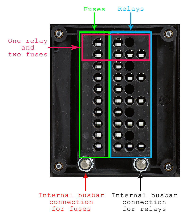
Considering the fuses, you’ll see that there are two cavities on the top side for the terminals, yet there is only one on the bottom. This is because one leg of each fuse is connected to the internal busbar, and the other leg is available to connect a female terminal and wire to.
With regards to the relays, you’ll observe on the top side five cavities for the male terminals of each relay. On the bottom, there are five as well, but they don’t exactly line up with what’s on top. This is because one terminal inserted into the top is connected to the second internal busbar. Also, there is another cavity on the bottom that isn’t accessible from the top-side with this specific enclosure model. This is because there’s a sticker on the top surface that blocks this hole.
This might all sound confusing at the moment, but study the following picture. It should clear things up.
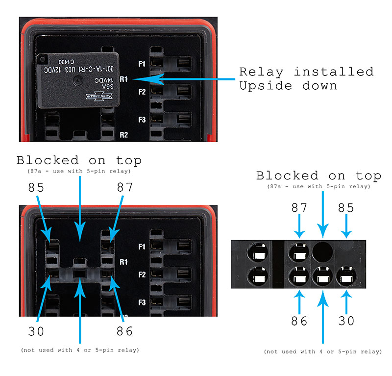
With this setup, power is supplied to your switch inside your vehicle and connects to pin 86 when the switch is engaged. This circuit will connect to your in-dash fuse block with a fuse tap, which protects this wire. Next, pin 85, which needs to be connected to ground, is connected to the internal busbar. Therefore, we will use the second internal busbar for grounding pin 85 on all relays. This is a simple setup, which limits the wires traveling through the firewall to six. It also makes each relay circuit live only when your ignition is on.
As a side note, if you chose to use a 5-pin relay, then pin 87a would be in the top-center position, but this is currently covered up with the overlaying sticker. In order to insert the terminal, you simply need to cut out part of the sticker that covers the cavity.
Connections
Now that we know how to wire an accessory to a relay and we know we’re going to install the relays upside down, we can use the following diagram to illustrate how to connect them to the Bussmann RTMR.
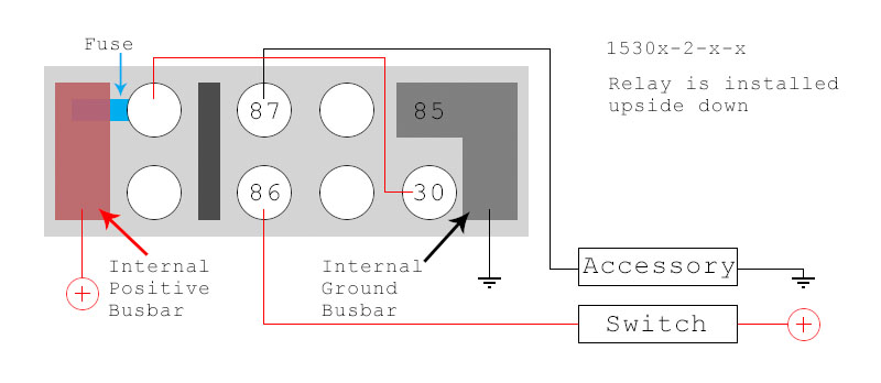
Notice that we only use one fuse, which supplies power to pin 30 through a short length of wire. This will be a high current signal, which continues through the relay’s internal switch and out pin 87 to the accessory.
The accessory is connected to pin 87 with a custom length of wire depending on the its location.
Your switch is connected to pin 86 and with a wire routed through your vehicles firewall.
Pin 85 is the switch ground and is connected to the second internal busbar.
The two additional middle cavities for the relay are not used.
Therefore, you only need three wires per relay connected directly to the Bussman RTMR to connect an accessory. I’ll show you how to make all of these wires with crimped terminals in the next part, Part 5 – Building the RTMR.
Accessory Grounds
There is another wiring issue to consider, though, and that is with regards to your accessory grounds. You have options here, but some are better than others.
One popular technique, although not highly recommended, is to connect the accessory ground at a nearby location, such as the vehicle frame or body. This isn’t recommended due to the ground point being inconsistent or of lower conductivity.
A second option is to connect all accessory grounds directly to the battery. Although this might provide a perfect ground, the side effect is messy wiring, and it somewhat defeats the purpose of installing a fuse/relay block.
A third option is to group all of the accessory grounds together. I’ve seen other installations where the ground wires are simply bundled or spliced together. Although this may work if the wire gauge is rated to handle the combined load, I feel it looks unprofessional and has the potential to be unsafe.
The final and preferred option, is to use busbars external to the Bussmann RTMR to attach your grounds to. I find this safer, more reliable, and a cleaner way to route your accessory grounds. I’ll detail the specifics with regards to installation and connection in Part 5 – Building the RTMR.
Wire Gauge
Now that you know how to connect everything together, you just need to know what size wire to use. Simply put, you use a wire gauge rated to handle the current of your accessory. Unfortunately, when trying to find the answers to this question, you’ll quickly see that there are many conflicting charts. This is because there is no single definitive chart for our application, and because there are many factors that go into ampacity rating. Wire length, ambient temperature, insulation type, and free air space are all contributing factors in addition to the cross-sectional area of a wire.
So with that said, this is a conservative chart that will accommodate our needs:
18 gauge – 7 amps
16 gauge – 10 amps
14 gauge – 15 amps
12 gauge – 20 amps
10 gauge – 30 Amps
Notice how I am not listing any wire size smaller than 18 gauge. This is intentional. I don’t want to use wire smaller than 18 gauge, because it can be a bit difficult to work with while using the Bussmann RTMR.
When wiring the RTMR, there are two circuit types: accessories and relay coils. The current requirements for the relay coils are many times less than the accessories. Furthermore, the coils are a known and constant rating, no matter what type of accessory is installed. As stated earlier and outlined in the datasheet, the current needed to energize the relay coil is 97.5mA at 12 volts. I also stated that I don’t want to use any wire smaller than 18 gauge. Therefore, I’ll be using 18 gauge wire to connect the switches to pin 86 of each relay. This is more than sufficient to handle the relay coil load.
With regards to connecting accessories, there are two different approaches to wire size selection when wiring the RTMR. One approach is to plan everything out in advance, with all of our accessories and current demands known beforehand. This would allow us to build the RMTR with the exact size wire we need for that specific accessory. You then build the enclosure and connect your accessories to the specific circuit where you want your switch. Great! But this doesn’t allow you to modify, adapt, or upgrade anything easily in the future. Therefore, the second approach is to build the RTMR so that each circuit can handle the maximum load that you may need, regardless of how many high-powered accessories you plan to install. Let me explain.
If I wire three of the circuits with 14 gauge wire and only two with 10 gauge, then I’m restricted to two circuits that can accommodate high-powered accessories. Furthermore, I’m also restrained on where the switches for these specific accessories are in my vehicle. This is the nature of the beast. Let’s say the first two relays are wired with 10 gauge. That means only the first two switches connected to these relays can be used for these accessories. But what if I wanted to reorganize my switches? What if I wanted to upgrade or swap out for a higher-powered accessory? This is where the other wiring approach comes in.
If I wire all five circuits of the RTMR with 10 gauge wire, then I have much more flexibility. I’m not limited to the number of accessories (within the five), and I’m not restricted to which circuit that accessory can be on. This means that I can choose any switch in my vehicle at any time. To swap accessories around, simply connect the accessory to a different circuit and change switch rockers. The wiring and switch bodies all stay in place. I know it can handle the load, because I’ve wired up the RTMR from the beginning to do so.
Now there’s a big warning here. The Bussmann RTMR is rated to a maximum of 80 amps. This is for each internal bus. The first internal bus is providing power to all ten fuses, and the second internal bus is providing ground for the switches. With five switches only needing 97.5mA each to energize the relay coil, this bus will never go over 1/2 amp, so it’s not of concern. However, we cannot go over 80 amps for the first internal busbar, which supplies power to all ten fuses.
So keep in mind that for all accessories, whether they’re connected through the relays or directly to a fuse, you cannot go over 80 amps. This does not mean you cannot connect accessories that total more than 80 amps when combined. It just means that you cannot use them all at the same time when their combined total will go over 80 amps. There is a clear distinction here. Therefore, your choice is to be very careful when using multiple accessories at the same time or to total their power requirements when purchasing so that they don’t go over 80 amps.
This might sound confusing, but you just have to do a bit of math and thinking beforehand. In a real-world application, you most likely won’t be hitting this 80 amp ceiling, but you’ve been warned.
Connectors
To allow for maximum flexibility, I’ll be installing Metri-Pack 280 Series connectors for the accessory wiring. This is what will make installing or swapping accessories very easy. Without this connector, your hands are still tied, even though we’re using 10 gauge wire. The accessory wiring would be a direct connection to the RTMR, so modifications would require the enclosure to be removed from the vehicle. This isn’t very flexible.
I’m choosing to use Metri-Pack 280 Series connectors instead of Weather-Pack connectors, because they have a higher current rating. Whereas Weather-Pack connectors are rated at 20 amps, Metri-Pack 280 Series connectors are rated at 30 amps. Therefore, they are a perfect match when using 10 gauge wire.
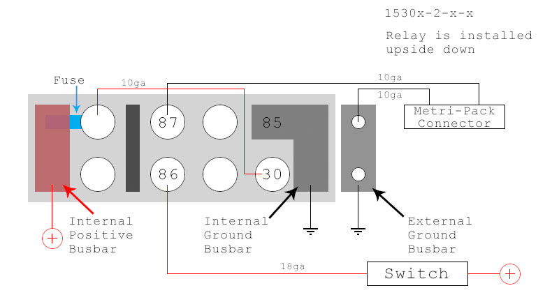
When installing the Metri-Pack connectors, I’ll run a positive wire from pin 87 to the connector and a ground wire from the external ground busbar to the connector. Both of these will be 10 gauge wire. This connector is your direct attachment point for an accessory. Look at the following diagram where I’ve updated it to show the external ground busbar, wire sizing, and connector.
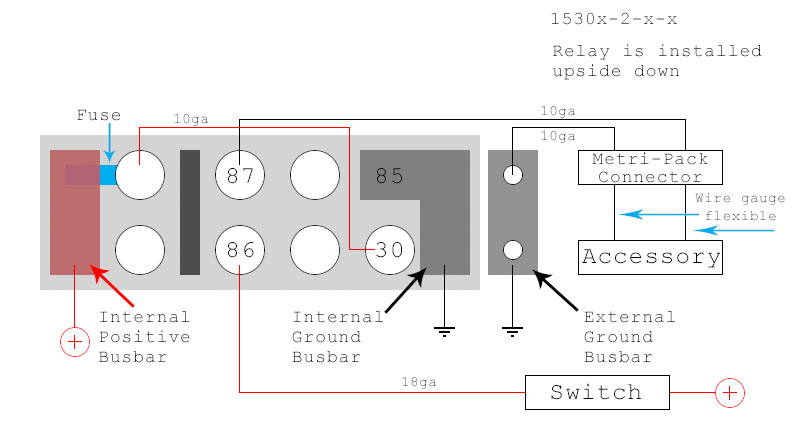
Now the cool thing is that when installing an accessory to the Metri-Pack connector, you’re not required to use 10 gauge wire between the accessory and the connector. Instead, you use the appropriate sized wire to connect your accessory to the Metri-Pack connector based on the need of that accessory. Then install a fuse in the RTMR for this circuit to match the wire size. Use the same chart I listed earlier when selecting fuse size.
18 gauge – 7 amps
16 gauge – 10 amps
14 gauge – 15 amps
12 gauge – 20 amps
10 gauge – 30 Amps
For example, if using 14 gauge wire for an accessory, install a 15 amp fuse. It doesn’t matter that the jumper wire from the fuse to pin 30 is 10 gauge or that the wires between the Metri-Pack connector and RTMR are 10 gauge. These have a higher ampacity rating, so you’re safe. The rule is that a fuse protects the wire. In this example, it needs to protect the smallest gauge wire in the circuit, which is 14 gauge.
With this new information, I’ve updated our wiring diagram once again to include the accessory. I’ve also indicated that the wire size from the Metri-Pack connector to the accessory has not been specified. You will make this choice based on your needs.
On a side note, I want to point out that fuse selection is important for not only the wire rating, but also the connector rating. I mentioned earlier my decision to use Metri-Pack connectors instead of Weather-Pack. If you were to use Weather-Pack connectors, then the highest rated fuse you could use is 20 amps, even if you used 10 gauge wire all the way out to your accessory. The connector has the lowest rating, so it trumps all other wiring.
Anyway, the flexibility of this design lies in the combined use of Metri-Pack connectors and 10 gauge wire for all direct accessory connections to the RTMR. It allows you to use any circuit for any accessory at any time. From this point, you can save a little money when installing wiring from the RTMR out to your accessory by using the correctly rated wire for that specific accessory.
One last note before concluding. I’ll be using is a six-way Weather-Pack connector for the switch wiring traveling through the firewall into your vehicle cabin. I’m using a Weather-Pack connector because a six-way Metri-Pack connector is not available, and it more than sufficiently meets our current needs. Anyway, the reason I used a connector for the switch wiring is for easy installation and any future troubleshooting. Once installed, you won’t be disengaging this connector, but if you ever need to remove the RTMR enclosure, you want to be able to do so easily without cutting any wires.
Conclusion
The following list summarizes what we’ve learned in this part.
- I’ve explained how a relay works, that it’s a device that uses a low-powered circuit to control a high-powered circuit.
- I’ve detailed the specifics of the Bussmann RTMR enclosure. You know which relay terminals the cavities align to.
- The relays will be installed in an upside-down position. This allows you to use the secondary internal busbar as a ground point for pin 85 of the relays.
- I’ve shown you a wiring schematic that details how to connect accessories and switches to the RTMR.
- We’ll be using external busbars in conjunction with the Bussmann RTMR to use as grounding points for all accessories.
- We’ll be using 18 gauge wire for the switches to pin 86.
- We’ll be using Metri-Pack 280 Series connectors rated at 30 amps with accessory wiring. This will allow future flexibility with swapping or upgrading accessories to different circuits.
- We’ll be using 10 gauge wire for the jumper wires from the fuse to pin 30.
- We’ll be using 10 gauge wire for the wiring from the RTMR and external ground busbars to our Metri-Pack connectors. This will allow for maximum current rating on all circuits and maintain a flexible design.
- Fuse selection is made based on protecting the wire. The fuse needs to be chosen to protect the smallest gauge wire for each circuit.
- We’ll be using a six-way Weather-Pack connector for the switch wiring running through the firewall and into the vehicle cabin.
In Part 5 – Building the RTMR, I’ll will walk you through building the RMTR in detail, step by step.